

This is the start-to-finish installation of a roof-mounted Poynting 7-in-1 MIMO antenna (4 x cellular, 2 x Wi-Fi, GPS) and a GL.iNet GL-X3000 router in our Ford Transit van.
Our Starlink Mini covers most of our internet needs on the road, but not all of them: under heavy tree cover it struggles, and that’s exactly where cellular takes over. The catch is that a cellular modem inside a metal van doesn’t hear much — so the antenna goes on the roof, and the router ties everything (Starlink, cellular, Wi-Fi) into one network with automatic failover.
Material and Resources
Time
4 hours
Cost
$750 USD
antenna + router + cable seal
Weight
4 lbs
Material
| Item | Description | Quantity | Buy |
|---|---|---|---|
| Poynting MIMO Antenna 7-in-1 | 2 x Wi-Fi, 4 x Cellular, GPS. | 1 | Amazon |
| Poynting MIMO-3 Antenna Mounting Bracket | Custom made to mount the Poynting Antenna to 80/20 crossbars. | 1 | FarOutRide |
| GL.iNet GL-X3000 Router | Wi-Fi router with automatic failover: Starlink (Wi-Fi or Ethernet), Cellular (SIM and eSIM), Wi-Fi (repeater), tethering. | 1 | Amazon |
| Scanstrut Multi Cable Seal | To pass the MIMO antenna’s 7 cables through the roof | 1 | Amazon |
| 3D-Printed Drill Template | To space the bung holes evenly when drilling the cable seal. STL file coming soon! | 1 | FarOutRide |
| DC Power Pigtail | 5.5 x 2.1mm female, to power the router from a 12V circuit. | 1 | Amazon |
| Stainless Bolts, Washers & Nuts | 6-32 x 3/4″ flat head, to fasten the cable seal base (replaces the included sheet metal screws). | — | Bolts Washers Nyloc Nuts |
| Silicone Sealant | To wet-install the cable seal fasteners. | 1 | Amazon |
| Rust-Preventative Primer | To protect the cutout’s bare metal edges. | 1 | Amazon |
Tools
- Power drill with 11/64″ bit and 5/32″ bit.
- Jigsaw with blade for metal.
- Safety glasses.
- Automatic center punch.
- Step drill.
- Deburring tool.
- Silver sharpie.
- Utility knife.
- Sandpaper.
- Hex keys and wrench.
- Isopropyl alcohol.
- Freezer (yes, really).
Good To Know
Which setup do you need?
This build is the full meal deal — most people don’t need all of it. It stacks in four tiers:
- Phone hotspot alone ($0): weekend trips with cell coverage. You already own it, there’s nothing to install. Its limits: hotspot data caps, and no cell coverage means no internet.
- Starlink dish alone: you camp beyond cell coverage, or stream more than your plan allows. The dish’s built-in Wi-Fi covers a van just fine. This is most people: see our Starlink installation (options A and B) and skip the rest of this post guilt-free.
- Add the router (~$380): full-time travel — one van-wide Wi-Fi network that fails over between Starlink, campground Wi-Fi, and your phone on its own; devices never need re-connecting. Stock router’s antennas, no holes in the roof.
- Add the roof antenna (~$350): you depend on internet (video calls under tree cover, uploads from town, low latency work) — the roof MIMO antenna is what makes cellular genuinely usable inside a metal van. That’s the build documented here.
Why this setup
We work from the van, so “mostly connected” doesn’t cut it. Our Starlink Mini covers most of the need, but it wants a clear view of the sky — and our favorite campsites tend to have trees over them. In town it’s the opposite: buildings block the sky, but cellular coverage is excellent. No single source works everywhere, so the goal of this setup is redundancy without babysitting.
The obvious backup is cellular, but there’s a catch: a van is essentially a rolling Faraday cage. A router sitting inside the metal box, using its stock antennas, leaves a lot of signal on the table. The Poynting antenna moves the four cellular elements onto the roof, outside the cage and up high where reception actually happens. Why four? The router’s modem has four antenna ports and uses MIMO (multiple-input, multiple-output) — several parallel signal paths to the same tower — so all four elements contribute to bandwidth, not just backup.
The two Wi-Fi elements do the same job for Wi-Fi: they let the router repeat a campground’s (or our driveway’s) Wi-Fi from farther away than any device inside the van could reach on its own. The seventh element is a GPS antenna — but as we found out during the installation, the X3000 has no GPS port to plug it into, so it stays unconnected for now.
- Starlink Mini: primary source, anywhere with open sky.
- Cellular (SIM/eSIM): backup in the trees, often faster in town.
- Wi-Fi repeater: campgrounds, cafés, home driveway.
- USB tethering: last resort, courtesy of our phones.
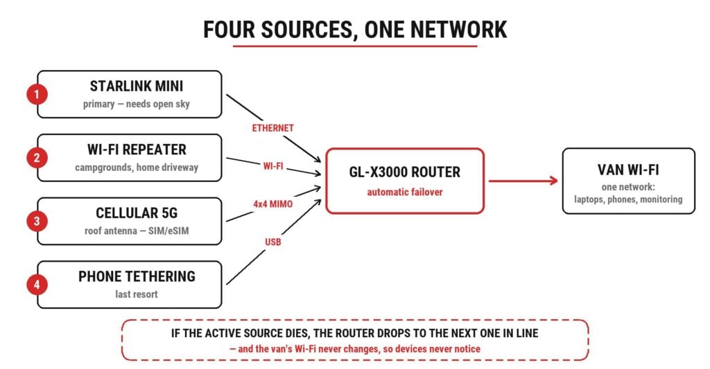
The GL.iNet X3000 router is the piece that ties it all together: it takes every source above and presents them as one network inside the van, with automatic failover. When the dish loses the sky, the router switches to cellular and our laptops never notice. We’ll go through the configuration in the Router Setup section below.
If “cellular booster” came to mind: we’ve been there. FarOutVan 2 originally carried a WeBoost booster on a motorized tilt antenna. A booster amplifies a single signal path and re-radiates it inside the van — its specialty is making any phone work on a weak fringe signal, voice calls included. But we don’t make phone calls; we need data, and we expected more from four roof elements feeding the modem in parallel than from one amplified path. So the WeBoost came off and this antenna took its place. If a booster fits your needs better, our install is fully documented:

Cable lengths
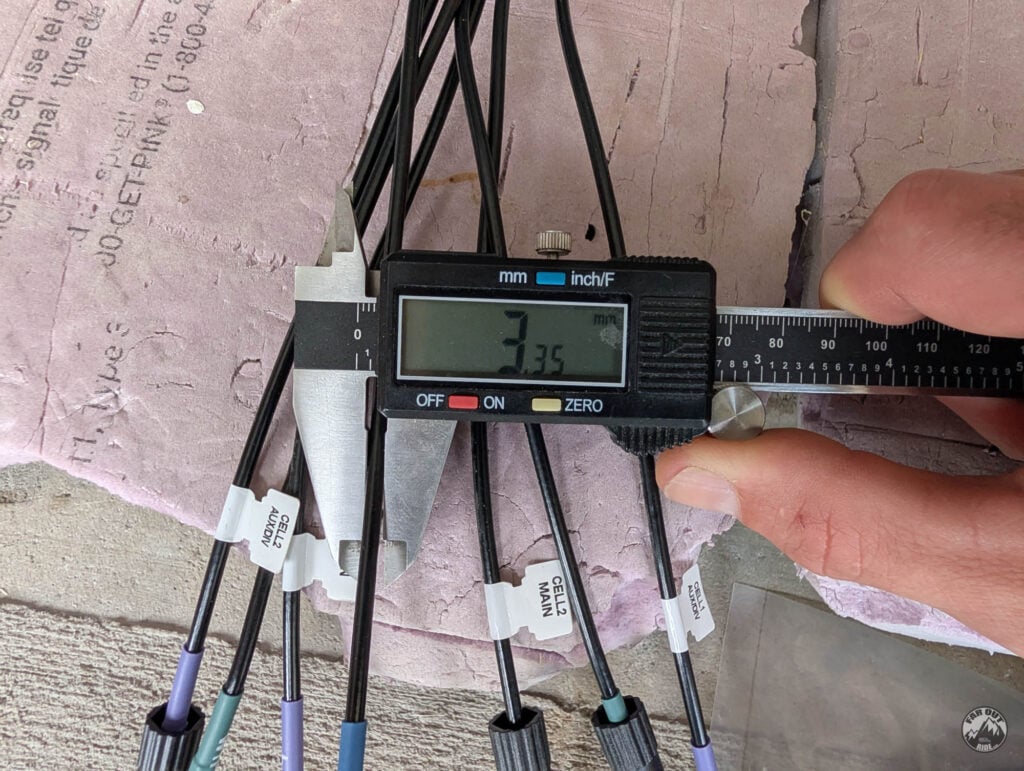
The Poynting MIMO-3-17-B antenna’s cables are 2 meters (6.5 feet) long. Use the shortest cable length necessary to reach your router. The stock antenna cables are thin (3.35 mm), and thin coax is lossy at high frequencies. While they can be extended, every extra foot reduces your signal, especially for 5G and Wi-Fi.
We installed the antenna in a straight line above the router, and with the router roughly 3 feet above our floor, we were able to use the stock cables without extending them.
Cable Seal Installation
For a single-round cable, our favorite solution is still the Cable Entry Pad (no-drill, no-screw, hassle-free). But the Poynting antenna has 7 cables, so we’re using a Scanstrut Multi Cable Seal as follows.
Preparation
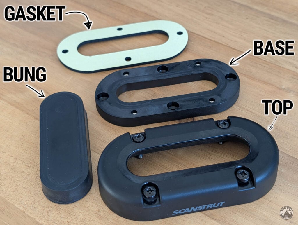
The Scanstrut Multi Cable Seal consists of a top, base, bung & gasket:
The bung is drilled to your cable diameters, and a slit allows for routing the cable from the side, making it compatible with any connector size:
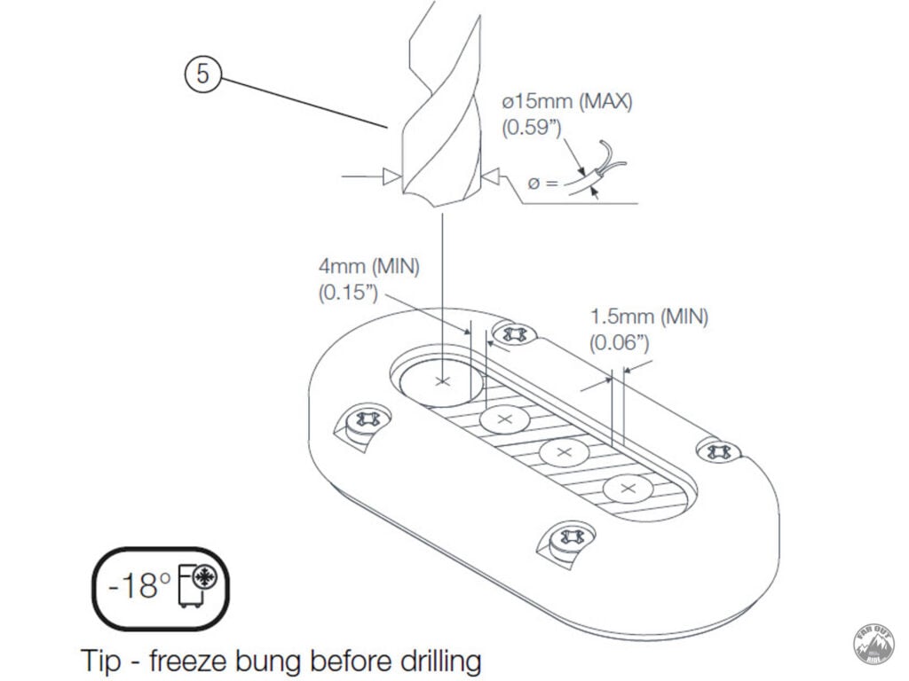
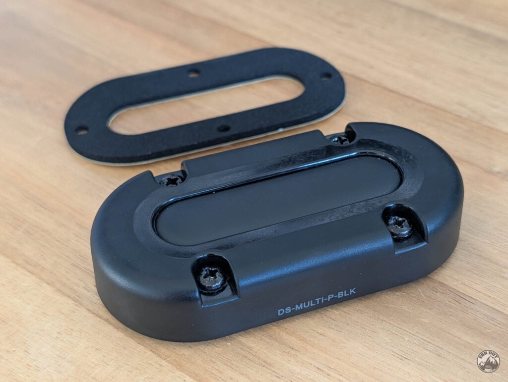
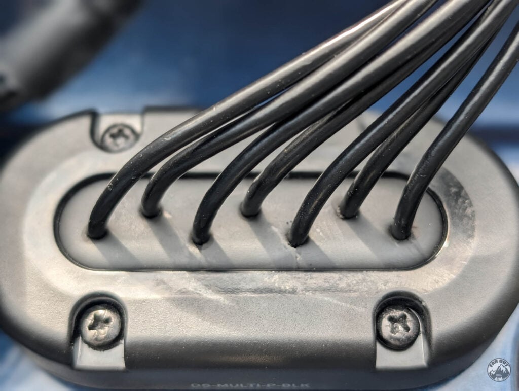
Tightening the top screws compresses the bung around the cable, making it IP68 waterproof:
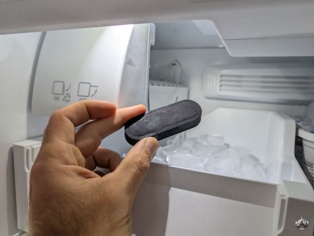
To help with drilling (accurate diameter and clean edge), place the bung into your freezer for a few hours:
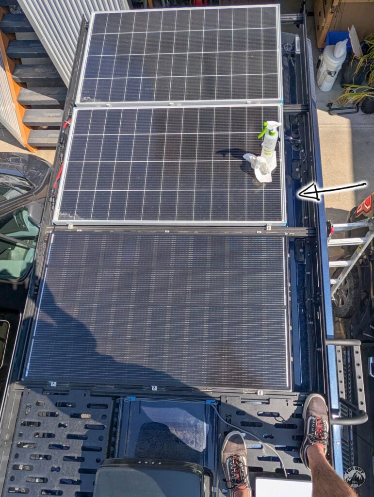
Clean the working surface with isopropyl alcohol:
Drill the screw holes
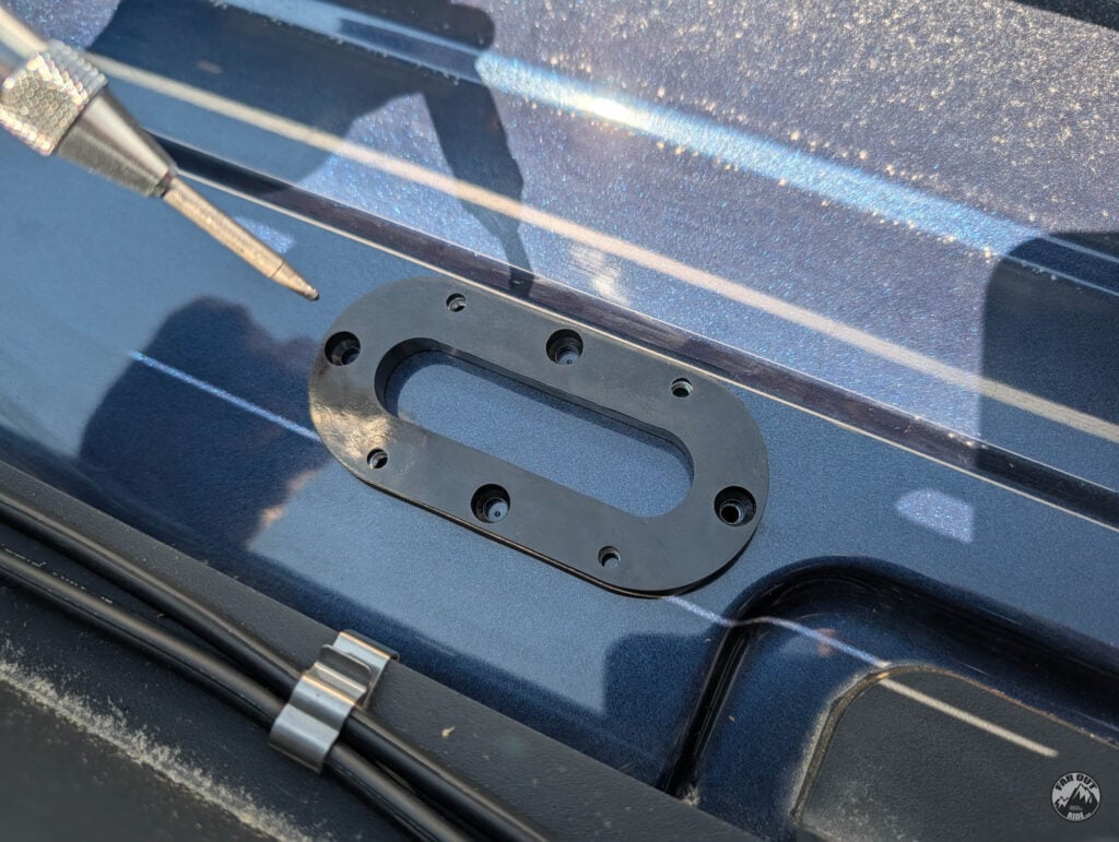
Using the base as a template, we used an automatic center punch to mark the center of the holes:
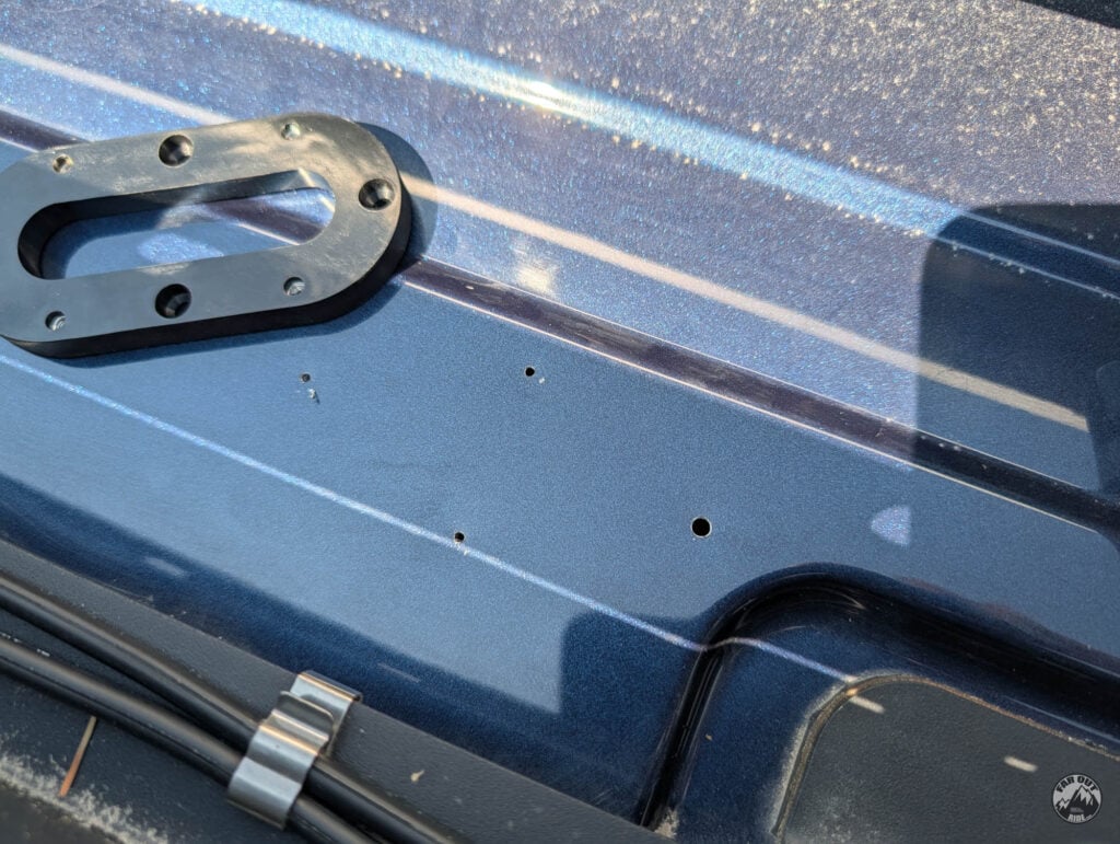
We drilled with an 11/64″ drill bit:
We used a deburring tool to clean the edges:
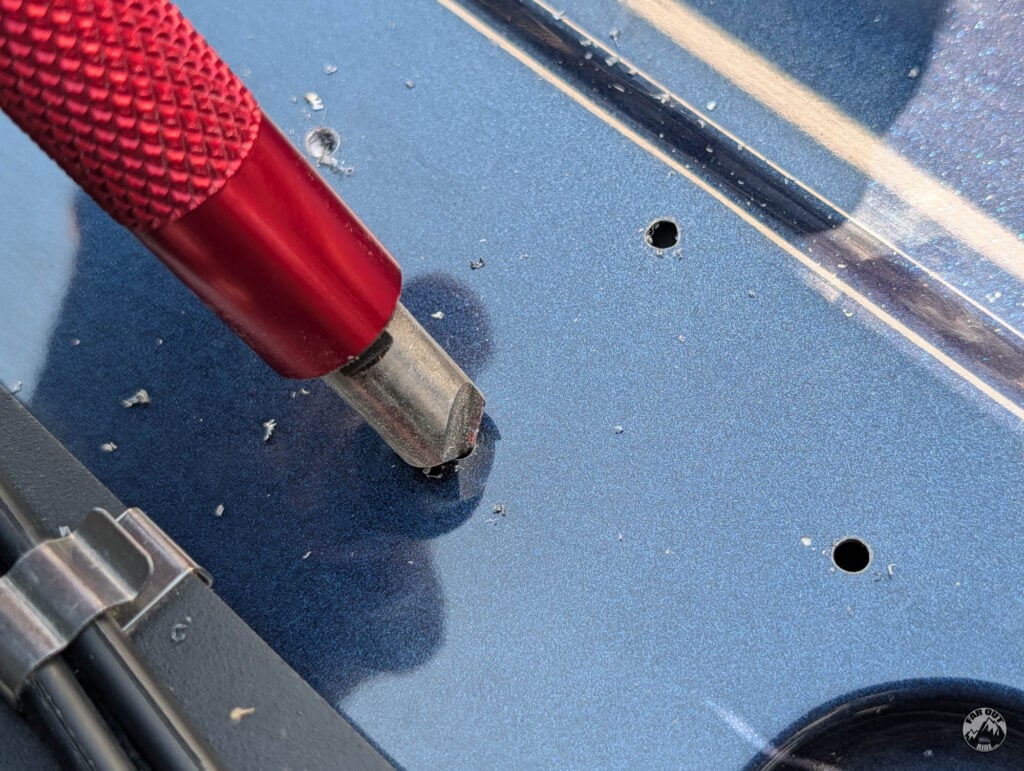
Make the cutout in the roof
We marked the centers of the cutout:
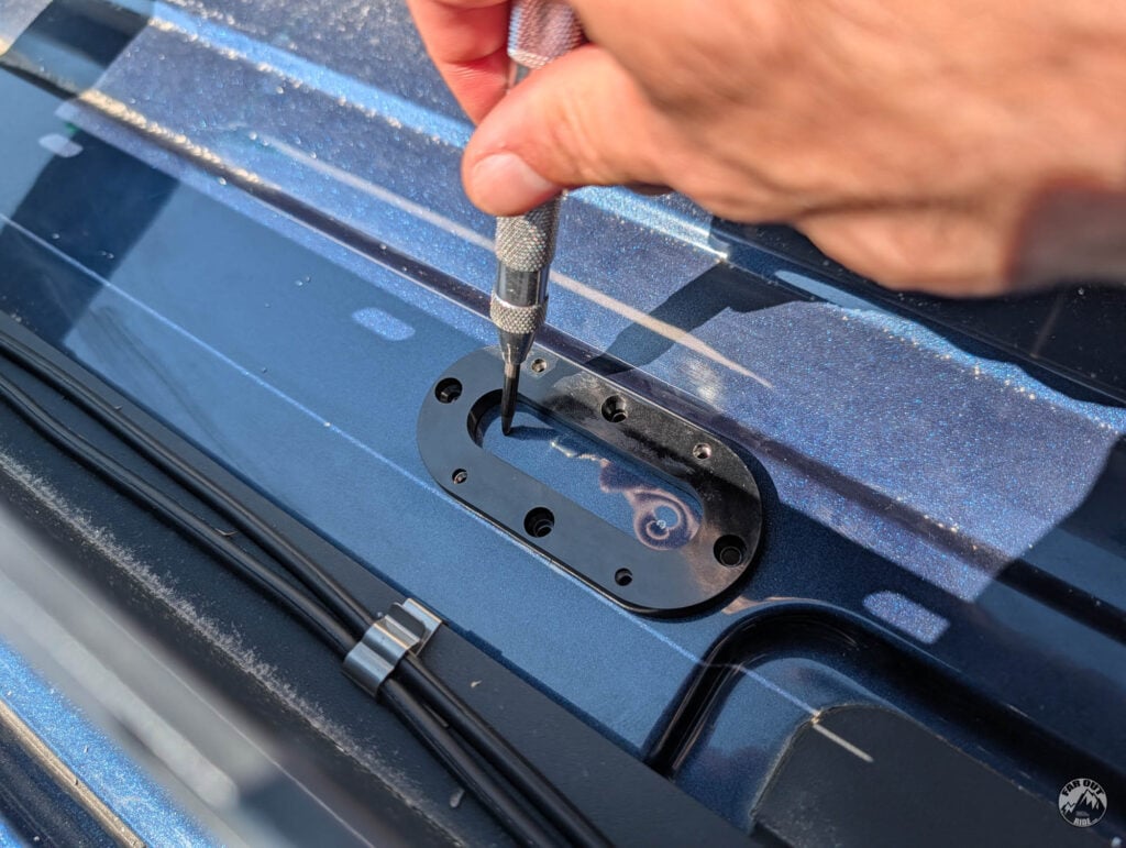
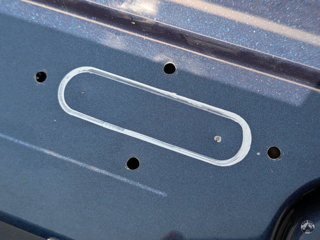
We traced the contour of the cutout with a silver sharpie:
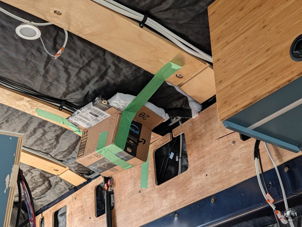
It’s a good idea to tape a box underneath, to catch the metal shavings:
We used a step-drill to open the holes:
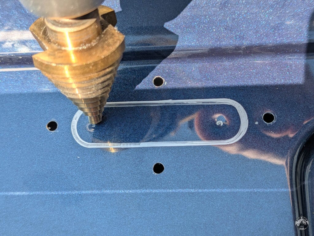
Mask the surface with tape before cutting the cutout:

Wear safety glasses. There’s no such thing as “it’s just a quick cut, it’ll be fine”. It was NOT fine:
A few hours later, after having metal removed from inside your eye, smooth the edges (deburring tool, sanding paper) and apply rust-preventative primer:
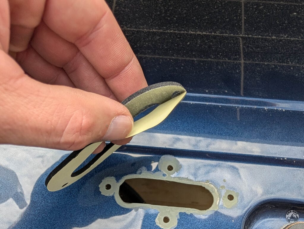
Remove the film from the gasket, and stick over the cutout. Did we mention we suck at working with metal?
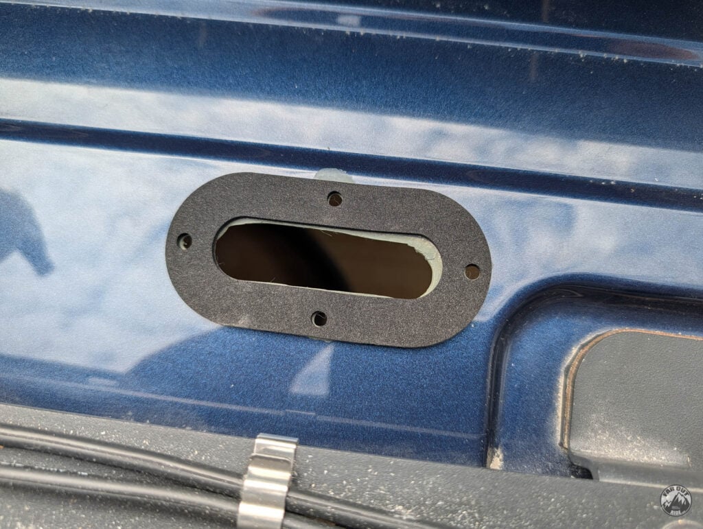
The Scanstrut multi comes with sheet metal screws, but we’re not fans of those. We used stainless 6-32 x 3/4″ flat head bolts, washers, and nuts instead. The bolts are wet-installed (sealed) with silicone (per manual):
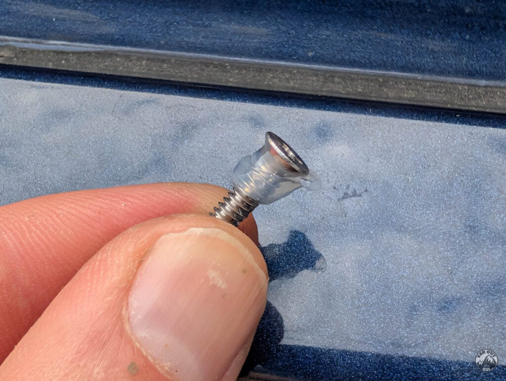
Ask Isabelle to install the washers and nuts from inside.
Wait, how did she get inside that cutout?
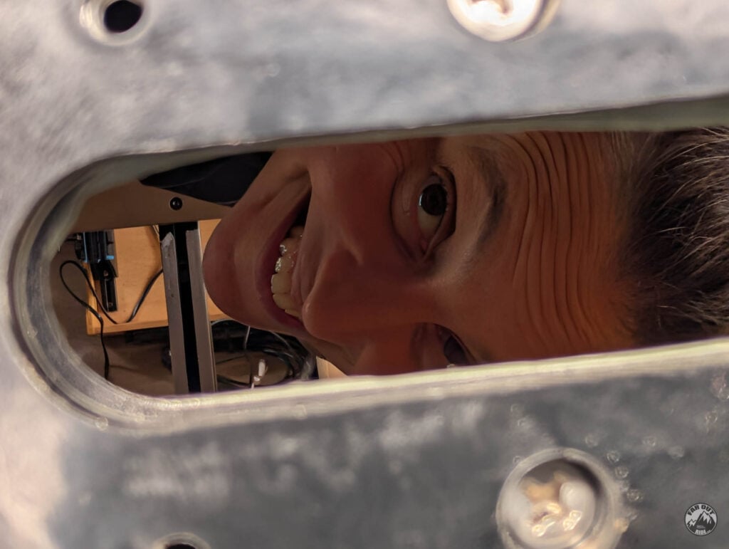
Nice:
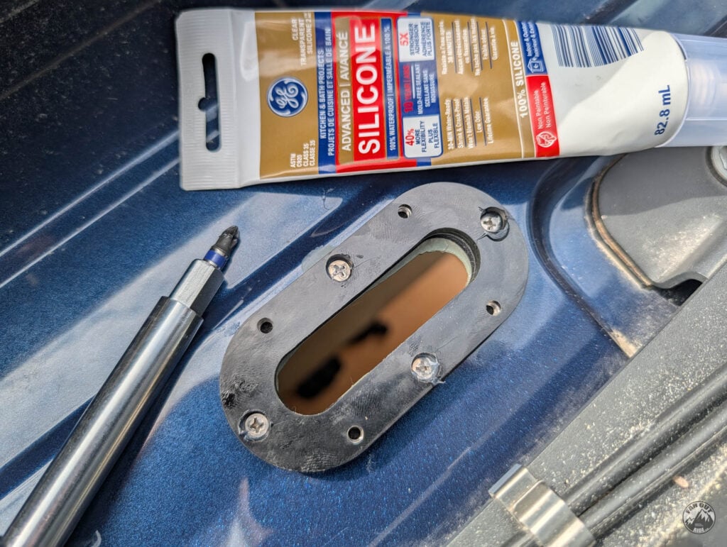
Inside:
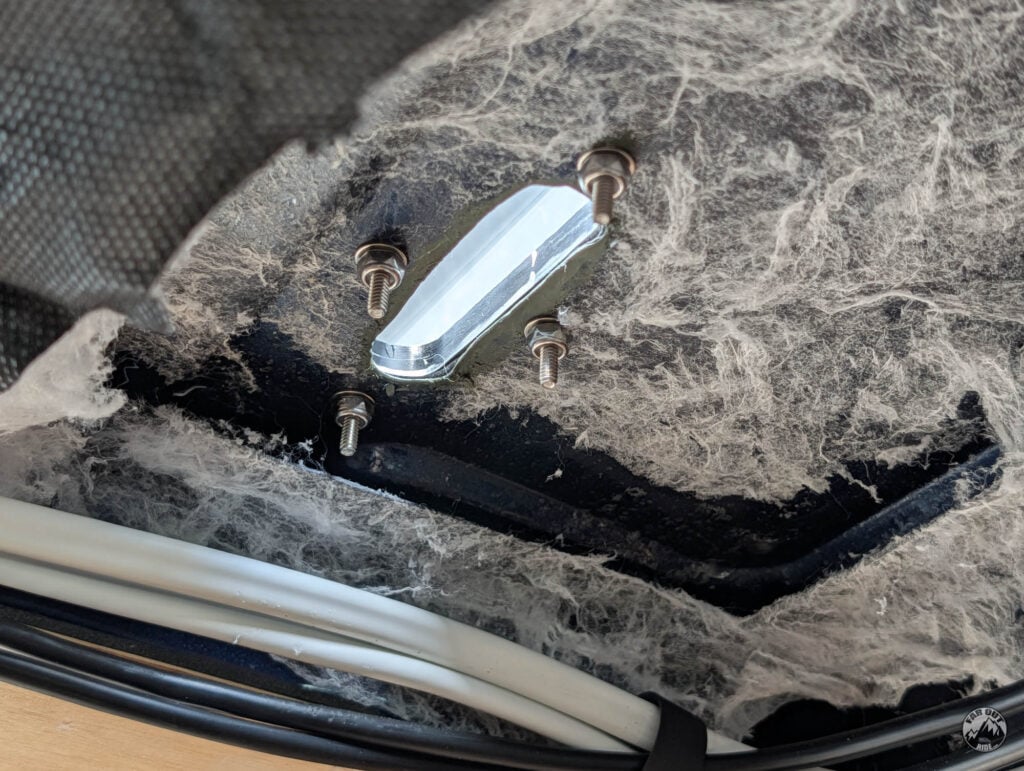
Drill the bung
The cable diameter is 3.35mm:
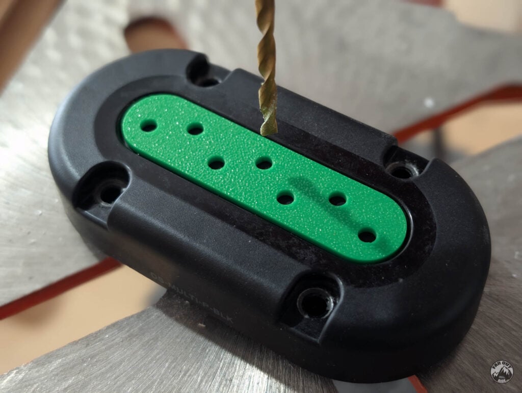
We made a 3D Printed Template to space the cables evenly and drilled with a 5/32″ bit:
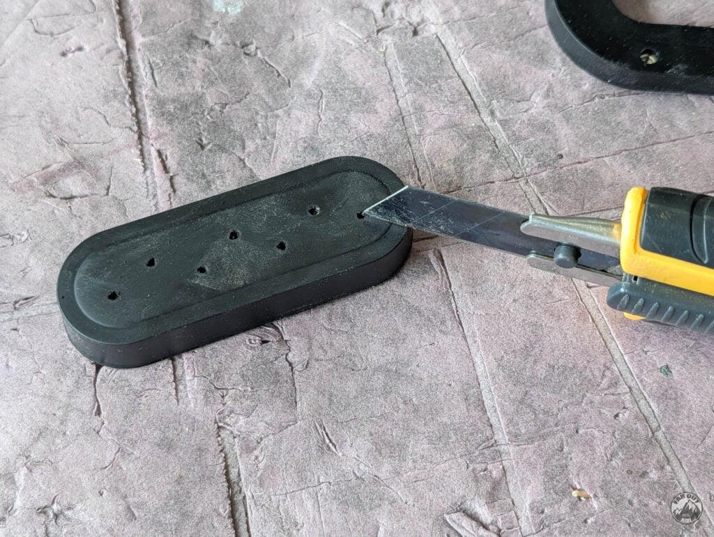
Using a sharp blade, we added a slit to each hole:
Route the cables
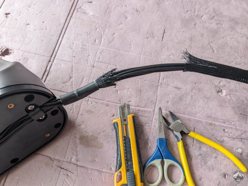
We trimmed the antenna’s protective sleeve:
We then routed the cables through the Scanstrut top cover:
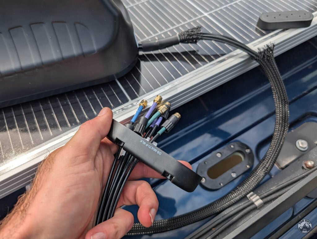
… and through the roof:
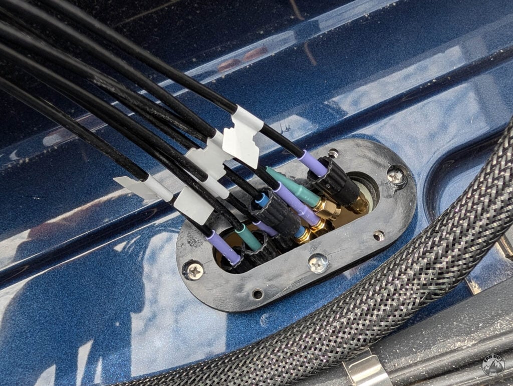
Leave some slack to move the antenna around:
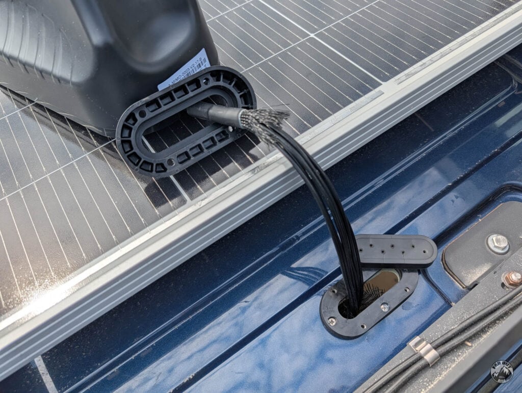
Slide the cables inside the bung:
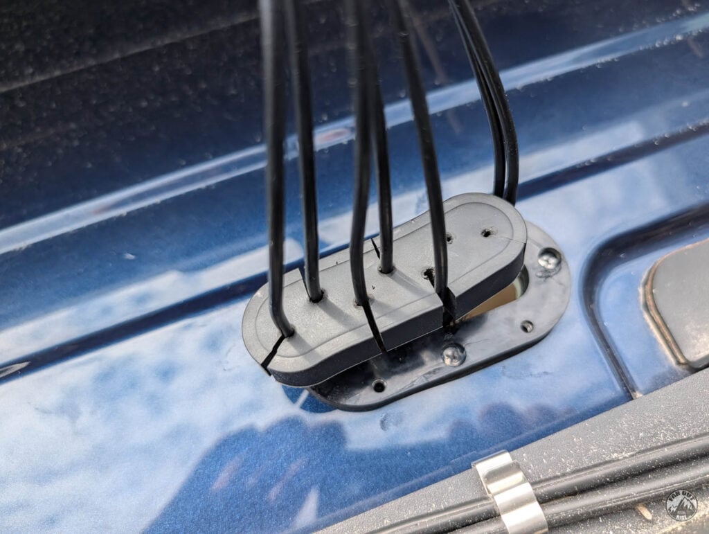
Screw the top
Insert the top. The fit is tight, we used a plastic tool to push the bung inside the top. At this point, we’re not too confident it’ll be waterproof… (the slits and holes are rough):
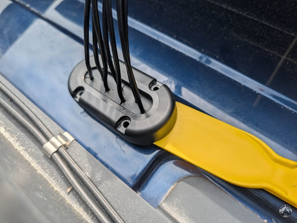
But after tightening the top part, the bung expands and seals the deal!
Antenna Mounting
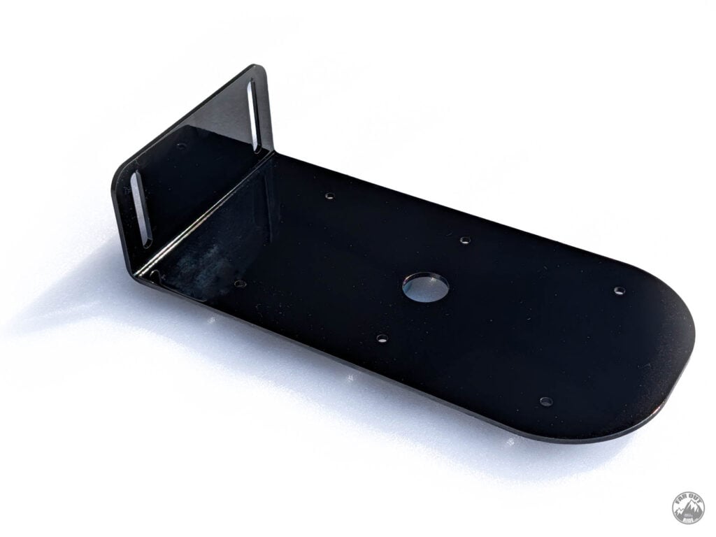
The Poynting MIMO antenna can be mounted onto a flat surface with self-adhesive pads, but we don’t have enough surface to work with here. So we designed a simple bracket that screws into the Flatline Van Co Roof Rack 80/20 crossbar (or any rack that uses 80/20 crossbars). The bracket is reversible, so the height can be adjusted with the antenna raised (maximum antenna reception) or lowered (to prevent partial shadows on the solar panels).
Prepare the cables
The antenna ships with a spigot installed. Remove it and route the cables using the provided clips:
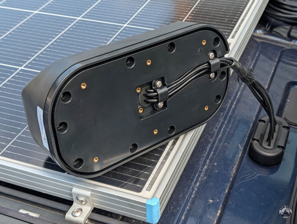
Install the antenna onto the mounting bracket
Use the provided foam gasket, but there’s no need for the adhesive backing here…
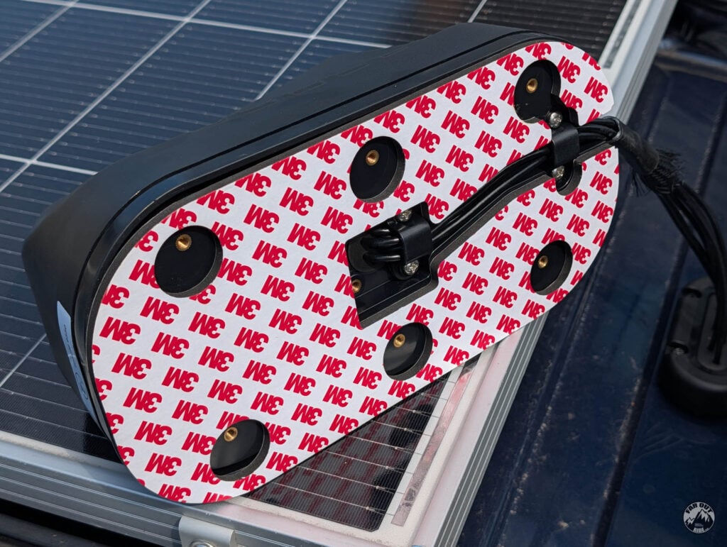
We used six stainless M4 x 16mm flanged button head screws to fasten the antenna to our Mounting Bracket:
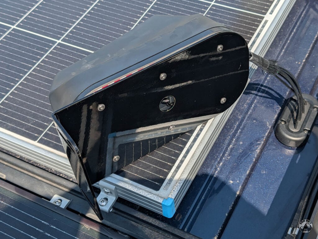
Install the mounting bracket to the roof rack
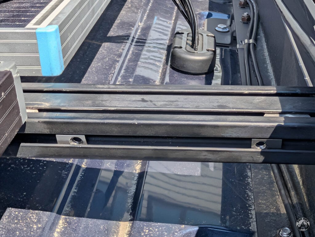
Insert two stainless 1/4-20 roll-in T-nuts into the crossbars:
Add blue Loctite to the threads (always use it with 80/20, to prevent the screws from loosening under vibration):
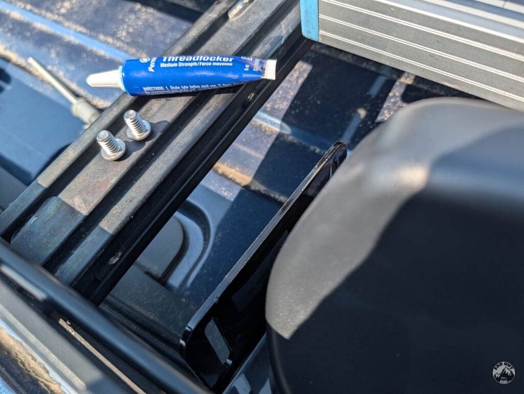
Fasten the Mounting Bracket with two stainless 1/4-20 x 3/8″ button head screws:
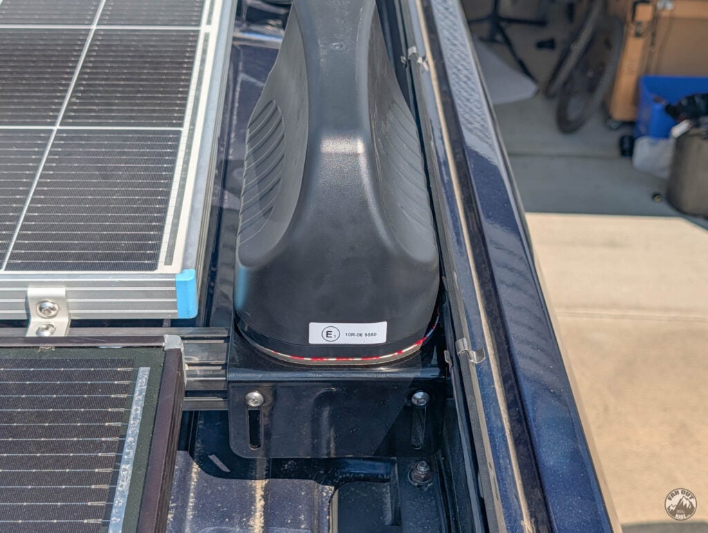
We’re done on the roof!
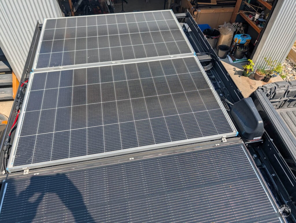
Router Installation
Router mounting
We mounted the GL.iNet X3000 router temporarily on some leftover plywood…
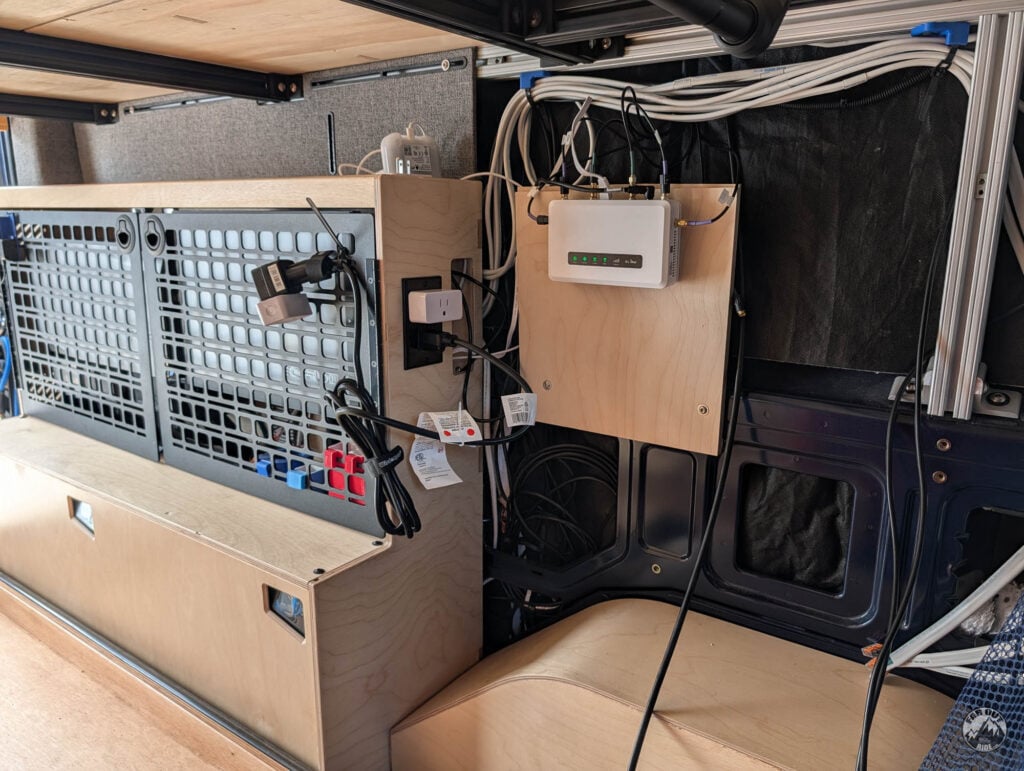
Connect the antenna’s cables
1. The 4 cellular cables are interchangeable. GL.iNet confirms the order doesn’t matter among MAIN / DIV/GNSS / MIMO 1 / MIMO 2 — no signal difference. So route them by whichever cable physically reaches each port most neatly.
2. The Wi-Fi cables need the included adapters. All 7 Poynting leads are SMA‑male, but the X3000’s two Wi-Fi ports are RP‑SMA. The antenna ships with SMA→RP‑SMA adapters in the box for exactly this — put one on each Wi-Fi lead. The 5 cellular/GPS leads screw straight onto the router’s SMA ports, no adapter.
3. The GPS cable is left unconnected, for now. The GL.iNet X3000 router doesn’t have a GPS port. We’ll figure out what to do with it later!
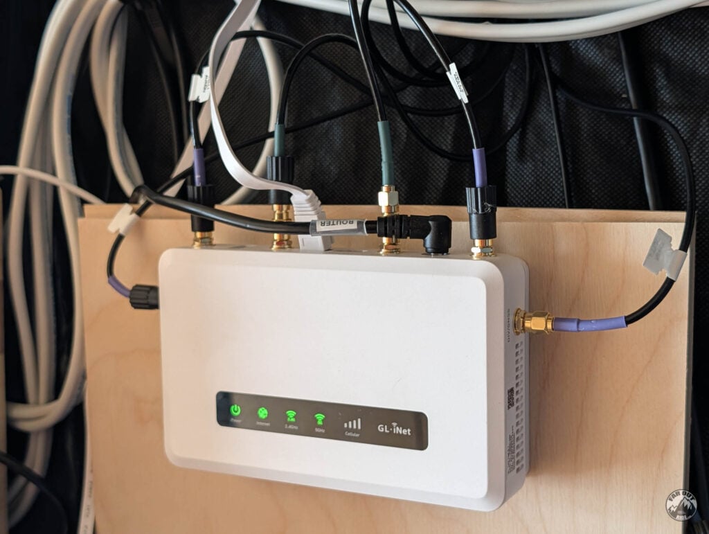
Power the router
The GL.iNet router includes a 120V power adapter. But as we know from our Electrical System Guide, converting power from DC (battery bank) → AC → DC (router) is not efficient (the inverter alone eats ~12%). So we’re powering it directly from 12V with a 5.5 x 2.1mm DC Power Pigtail wired to our Power Kit Distribution Panel.
Router Setup
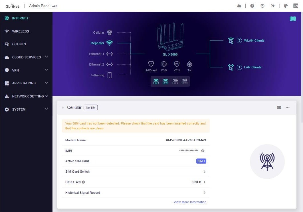
All the configuration happens in the router’s admin panel: connect to the van’s Wi-Fi and open http://192.168.8.1. The Internet page shows one card per connection type — we set up each source below, then tell the router which one to prefer.
Starlink
Two ways to feed Starlink to the router:
- Repeater: the router joins the dish’s Wi-Fi like any other network, and rebroadcasts it (“repeats” it).
- Ethernet (recommended): dish’s Ethernet port to the router’s WAN port. A cable is more reliable than Wi-Fi repeating Wi-Fi. It’s what we use.
Since the dish is hardwired, we added a static route to 192.168.100.1 on the WAN interface, so the Starlink app can still reach the dish through the router.
Cellular SIM/eSIM
Insert a nano-SIM and the router detects the APN automatically for most carriers; if it doesn’t connect, set the APN manually in the Cellular card’s settings.
The built-in eSIM is handy for travel data plans and border crossings: buy a plan, add the profile under Cellular → eSIM, done. Only one of SIM/eSIM is active at a time.
Wi-Fi Repeater
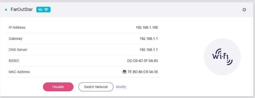
On the Repeater card: scan, pick a network, enter its password. The router remembers every network you’ve joined and reconnects on its own — enable Allow Switching to Other Saved Networks in the card’s options so it hops between saved networks without help.
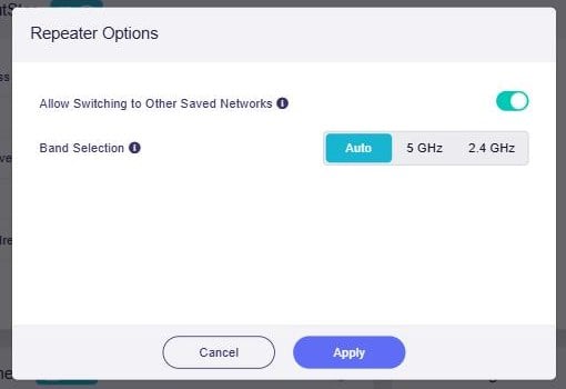
One subtlety: the repeater connects to a single upstream at a time. That’s one more reason we hardwired the dish — the repeater stays free for a campground network, with Starlink still connected over Ethernet.
Failover Priorities
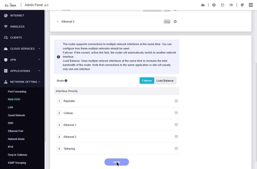
Under Network Setting → Multi-WAN, keep the mode on Failover (Load Balance splits traffic across sources — not what you want with a metered SIM) and drag the sources in order of preference. The router pings through the active connection every few seconds; when the pings die, it drops to the next source in line, and climbs back up when the connection recovers.
Real-World Tests
coming soon
Power Consumption
coming soon
Speed Test
coming soon
Our Verdict
coming soon




In the final picture of “4.3 Install the mounting bracket to the roof rack” (https://faroutride.com/wp-content/uploads/2026/07/MIMO-Antenna-and-Router-Installation-in-Van-38-.jpg), what is the cable running along the top of the driver side roof rack? It wasn’t installed in the earlier pictures of this guide, so was curious if it’s related or not.
To describe the cable more in the hopes of identifying it, the cable enters the picture at the bottom-right, travels along the top of the roof rack with clips, looks to come down into a circular bundle before ultimately entering the cabin via one of your custom cable entry glands where your old antenna was.
If I had to guess, this might be the Starlink Mini ethernet cable?
That’s the Ethernet cable, correct!
It’s currently routed but not connected (we’re on the road right now).
We will eventually remove the OEM power cable, and use the POE Ethernet cable instead. We left extra cable length (circular bundle) so we can just pick up the antenna and deploy it to the ground without disconnecting the cable.
Blue loctite should be used when mounting the bracket to the roof rack to prevent bolts loosening due to road vibration, right? I didn’t see it mentioned and thought it might be important to call out if warranted. Cheers.
Correct!
I added the instruction with a photo following this comment (not sure why I didn’t add it the first time?!).
Thanks for the heads up 🙂