This is the start-to-finish installation of the EcoFlow Power Kit GEN2 electrical system in our Ford Transit van.
The Power Kit is an all-in-one, plug-and-play electrical system for campervans and RVs. While building a DIY system usually takes days, you can get a Power Kit up and running in just a few hours! If you are not familiar and/or still debating between an EcoFlow Power Kit or making your own DIY system from scratch (e.g. Victron), we documented our decision-making here: EcoFlow Power Kit (Plug and Play) vs Victron (DIY) | Decision Time!
The system is installed and has been running for over a year — we’re still documenting the last sections and will update as we go!
FarOutVan 2 Electrical System
EcoFlow Power Kit 5kVA Gen2 with Console — it’s been on and running for over a year now: induction cooktop, oven, water heater, fridge, Starlink, charging our two e-bikes, and more. Fresh & grey water tank levels are monitored in the console.
If it’s the right fit for your build: 10% off with code FAROUTRIDE10 at Campervan-HQ (USA), or 5% off with code FOR5EF at TecVan (Canada, Gen1). With our code, this is usually cheaper than buying straight from EcoFlow. These folks know vans and are very responsive. Using our links/codes supports FarOutRide at no extra cost to you — thanks!
Disclosure: This post contains affiliate links, which means that if you click a product link and buy anything from the merchant (Amazon, eBay, etc.) we will receive a commission fee. The price you pay remains the same, affiliate link or not.

Material, Tools, Specs
Material
HEADS UP!
| ITEM | DESCRIPTION | QTY | BUY |
|---|---|---|---|
| EcoFlow Power Kit – USA | 50A RV GEN2 Power Kit with Console. 10% discount with code “FAROUTRIDE10” | 1 | Campervan-HQ |
| EcoFlow Power Kit – Canada | GEN1 Power Kit (GEN2 not available in Canada at the moment). 5% discount with code “FOR5EF” | 1 | TecVan.ca |
| 5kWh Battery | Optional additional battery (so 10kWh total). | 1 | Campervan-HQ |
| Power Link | To monitor tank levels, temperatures, etc. | 1 | Campervan-HQ |
| 48V A/C Cable | As required, to connect 48V appliances (air conditioner, etc). | 1 | Campervan-HQ |
| 2-Pole Main Circuit Breaker | Main circuit breaker in the Distribution Panel. | 1 | 30A 50A |
| 15A Duplex Breaker | Duplex breakers let you add two circuits per slot in the distribution panel. | 2 | Amazon |
| 20A Single Pole Breaker | To use with 20A outlets (e.g. induction, oven, or other high-power device). | 2 | Amazon |
| ALTERNATOR CHARGING | |||
| BlueSea 285 Circuit Breaker 120A | To protect the ALT IN cable and acts as manual ON/OFF switch | 1 | Amazon |
| Enclosure for BlueSea 285 Breaker | No exposed terminals, and clean wall mount. | 1 | FarOutRide |
| 4 AWG – 5/16″ (M8) Lug | To connect to Ford Transit CCP2. | 1 | Amazon |
| 4 AWG – 1/4″ Lug | To connect to the breaker. | 2 | Amazon |
| Grounding Hardware | To create a new grounding point and connect the ALT IN negative wire, and grounding wires for the Power Hub and the Distribution Panel. | 1 | Bolt Nut Grease |
| SHORE POWER CHARGING | |||
| Shore Power Inlet | We never go in campgrounds, but we still installed a 30A inlet just in case. If you are 100% sure to never use 30A shore, it is OK to install a 15A inlet. | 1 | 15A Inlet 30A Inlet |
| Shore Power Entry Box | Allows to add shore power inlet to the Ford Transit through existing cutout in the D-Pillar; no drilling required! | 1 | 15A Entry 30A Entry |
| Shore Power Adapter 30A Female to 15A Male | To plug a 30A shore power inlet to a “regular” 120V 15A Outlet at home. | 1 | Amazon |
| SOLAR CHARGING | |||
| 700W Solar Power | Products used and step-by-step installation: faroutride.com/solar | ||
| DC LOADS | |||
| Fridge | We had this same refrigerator/freezer in FarOutVan 1. | 1 | Campervan-HQ |
| Roof Fan | We personally have the Maxxair MaxxFan Deluxe 6200K. | Campervan-HQ | Amazon | |
| Wall Fan | The Sirocco Elite II fan is ridiculously priced, but we loved it so much in FarOutVan 1 that we want is again. It’s mounted on a gimbal (360 multi-directional), is VERY silent (brushless motor), and features 3-level and timer options. | Amazon | |
| Puck Lights | Same lights as FarOutVan 1, they’re great! We like the Warm White, which provides a cozy, soft atmosphere. | Amazon | |
| Light Strip | We recessed it under our upper cabinet. | Amazon | |
| USB Outlets | This specific outlet can power up to 100W on USB-C, and 18W on USB-A. | Amazon | |
| Water Pump | Shurflo Revolution 4008. 3 Gallon Per Minute, 55 PSI. | Campervan-HQ | Amazon | |
| Gas Heater | The Espar AS3-B2L is tapped to the Transit gas tank, and draw a minimum amount of current to power its internal fan and glow plug (startup only). | Our Guide | |
| AC LOADS | |||
| 15A Outlets | Located in electrical cabinet, kitchen countertop, water cabinet (for water heater), and at the front of the van (toilet cabinet). | 4 | Amazon |
| 20A Outlets | For induction cooktop and oven, although 15A would work too. We used 20A to have an extra buffer to charge the laptops on these outlets. | 2 | Amazon |
| 15L Water Heater (4 Gal) | The Isotemp Spa 15 is a dual-source water heater: Electric (AC 750W) and/or van’s coolant system. | 1 | Isotemp |
| Induction Cooktop | The Mini-Duo is one of the few units that modulate its power (constant low power), instead of pulsating (ON/OFF max power). | 1 | Amazon |
| Oven | We purchased this unit for the van, and loved it so much that we also got one for the house! | 1 | Amazon |
| POWER LINK (SENSORS) | |||
| RJ45 Ethernet Splitter | Required to wire communication cable to Power Link. | 1 | Amazon |
| Tank Level Sensors | See our Water System Installation Guide. | Amazon | |
| Temperature Sensors | NTC 10K/B3950 resistance-type. 3m cable. | Amazon | |
| OTHERS | |||
| Ferrules | To use on stranded wire that’s connecting into set-screw terminal. | VAR | Amazon |
| Heat Shrink Tubing (Red + Black) | To use when a ferrule or a terminal lug is added. | VAR | Amazon |
| Heat Shrink Tubing (Clear) | See Wire Labeling section. | VAR | Amazon |
Tools
| ITEM | DESCRIPTION | LINK |
|---|---|---|
| Wire Stripper / Cutter | To remove insulation from wires. | 12-22 AWG 6-12 AWG |
| Utility Knife | To strip insulation from heavy gauge wires. | Amazon |
| 10-in Cable Cutter | To cut large cables. | Amazon |
| Crimp Tool 8-22 AWG Single-Crimp | To crimp heat-shrink connector (single-crimp). | Amazon |
| Crimp Tool, Hydraulic 2/0-12 AWG | To crimp lugs and large ferrules. | Amazon |
| Ferrule Crimp Tool Hexagonal 5-28 AWG | To crimp ferrules on stranded wire. (Hexagonal is suited for round connectors featured on the EcoFlow Distribution Panel) | Amazon |
| MC4 Crimper Tool Kit | To pass solar cables through the roof (as required) | Amazon |
| Heat Gun | For heat shrink connectors and tubing. | Amazon |
| P-Touch | See Wire Labeling section. | Amazon |
| RJ45 Ethernet Cable Crimp Kit | Optional to shorten Ethernet cables. | Amazon |
Specs
| GEN 1 | GEN 2 | |
|---|---|---|
| POWER HUB | ||
| Dimensions | 18.9″ x 5.5″ x 11.8″ | Same dimensions |
| Weight | 31 lb | 34 lb |
| AC Out | 3600W | 5kVA |
| AC Voltage | 120V | 120V or 240V |
| Battery Ports | 3 Battery Ports (including 48V Output) | 3 Battery Ports + 48V Output |
| DC Out (max) | 70A | 100A |
| Solar Input | 15-150V 30A|30A|30A | 13-60V 60A|30A|30A |
| Alternator Input | 60A (PV Input 1) | 100A (PV Input 1) |
| Noise | ? | Reduced from (?) to 48 dB |
| DISTRIBUTION PANEL | ||
| Dimensions | 8.3″H x 13.9″W x 3.9″D | 15.3″ x 5.3″ x 10.6″ |
| Weight | 5.7 lb | 8.8 lb |
| DC Out | 12 DC Out (1-12: 20A) | 16 DC Out (1-13: 30A 14-16: 50A) |
| Controllable Circuits | 6 (1-6) | All 16 |
| AC Out | 6 AC Out (20A each) | 12 AC Out (30A each) |
| AC In | 30A AC Breakers (proprietary) | 30/50A AC Breakers (standard) |
| TOUCH-SCREEN | 7-in “Console” | 10-in “Power Insight” * Read note below table. |
| Power Link NEW! | Compatible with GEN 1 | |
| Voltage Sensors | 4 | |
| Resistance Sensors | 4 | |
| Digital Inputs | 1 | |
| Relays | 2 | |
| Power Dock NEW! | Compatible with GEN 1 | Adds 3 battery ports to any battery port on the Power Hub. So a total of 9 batteries can be connected to a Power Hub. |
| BATTERIES | No changes from GEN 1 to GEN 2. |
* We have reports from beta testers that the 10-in Power Insight draws a lot of power for itself, and as such, the 7-in Console may be a better choice for mobile systems (vans, RVs, etc.) to prevent phantom battery loss. Campervan-HQ now offers the 7-in Console as an option with the GEN2 Power Kits.
Weight
Weight breakdown of the EcoFlow Power Kit components:
| ITEM | WEIGHT |
|---|---|
| 2kWh Battery | 37.7 lbs |
| 5kWh Battery | 89.5 lbs |
| Power Hub GEN 1 | 31 lbs |
| Power Hub GEN 2 (5kVA) | 34.6 lbs |
| Distribution Panel | 8.8 lbs |
| Power Link | 0.26 lb |
| Console Display | 1 lb |
| Various cables | ~ 100 lbs (estimate) |
Specifically in our van, we’re looking at around 325 lbs (2 x 5kWh, Power Hub Gen 2, Distribution Panel, Power Link, Console Display, cables).
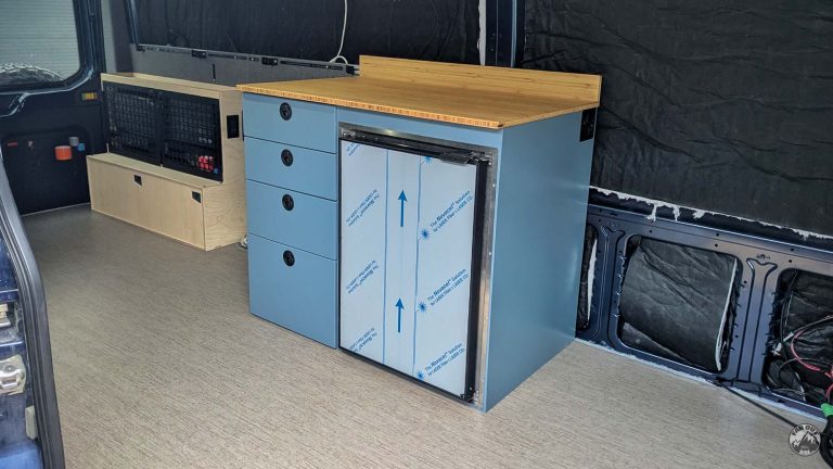
Cabinet
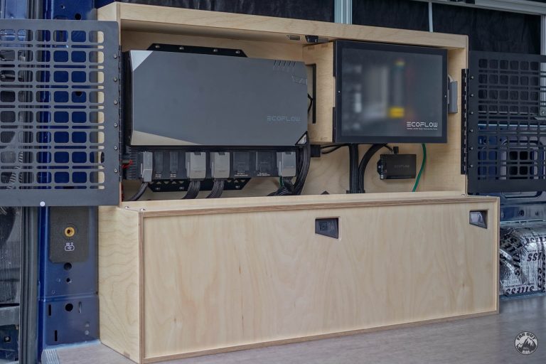
We installed our EcoFlow Power Kit at the back of the van, on the driver’s side, in a custom electrical cabinet. We have the Extended-Length Transit, so there is enough room for two 5 kWh batteries between the wheel well and the D-Pillar. Below is an overview of how we made the cabinet:
Before, without the electrical cabinet:
After, with the electrical cabinet in place:
The removable front panel makes it really easy to install the batteries in the cabinet:
Cabinet with Batteries, Power Hub (Gen2), Distribution Panel (Gen2), and Power Link (for tank level, temperature sensors):
The front cover slides down:
The top cover is screwed into rivet nuts (in an aluminum angle) and locks the front cover into place:
Top cover’s hardware:
To allow passive ventilation, we laser-cut MOLLE doors (aluminum, black textured powder-coated) with the same pattern as our Transit Rear Door MOLLE Panels, so that we can use the same accessories:
The doors are mounted with piano hinges and open 180 degrees for easy access to the components in the cabinet:
Same, but looking back (120V outlet shown):
To prevent rattling, the doors are preloaded into a soft TPU (rubber) Door Stop that we 3D printed:
At the bottom, we stuck an off-the-shelf soft bumper. We keep things simple when we can 🙂
The cabinet’s CNC and 3D Print files are available here:
Mounting
But first, unboxing:
Unboxing is oddly satisfying and shapes the things to come; everything is neatly packaged and organized. No components were damaged.
First glance at the hardware:
When I first saw the components, I could tell EcoFlow was founded by ex-DJI employees. Just like my Bambulab 3D printer. They share similarities. The hardware is very refined, and the material has a very high-end feel. All the included cables are protected in sheathing and conduit. An “Apple-like” experience. So far, it inspires confidence.

Batteries
The EcoFlow Power Kit comes with all the battery mounting hardware. It’s very well designed and should work for most people:

There’s nothing wrong with the included hardware, but we discarded everything, except the straps, and made our own to fit in our custom cabinet. We used an aluminum angle from the hardware store and cut it to the desired lengths:

There are 1.5mm deep channels underneath to provide a “path” for the battery straps:
Power Hub
Just like all EcoFlow’s components, the Power Hub comes with all the mounting hardware (and even a 1:1 template!).
A 1:1 template is included, making it very easy to locate the screw holes for the center, lower, and top brackets:

We install the center mounting bracket with #12 x 1/2″ stainless screws (the included screws were too long for 1/2″ plywood):

We then attached the lower & top brackets to the Power Hub (with the included screws), and then screwed the brackets to the cabinet with #12 x 1/2″ stainless screws:

Distribution Panel
The GEN 1 Distribution Panel can be surface-mounted to a wall using the provided hardware. The GEN 2 Distribution Panel (30/50A), however, must be flush-mounted through a 361mm wide x 241mm tall cutout:


Power Link
The EcoFlow’s Power Link (for tank level and temperature sensors) is surface-mounted to a wall, using two screws (we used #8 screws). Leave some space above for the communication cables, and some space below for the sensor wires:

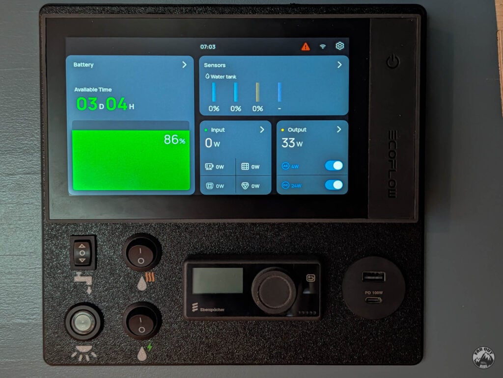
Console (Display)
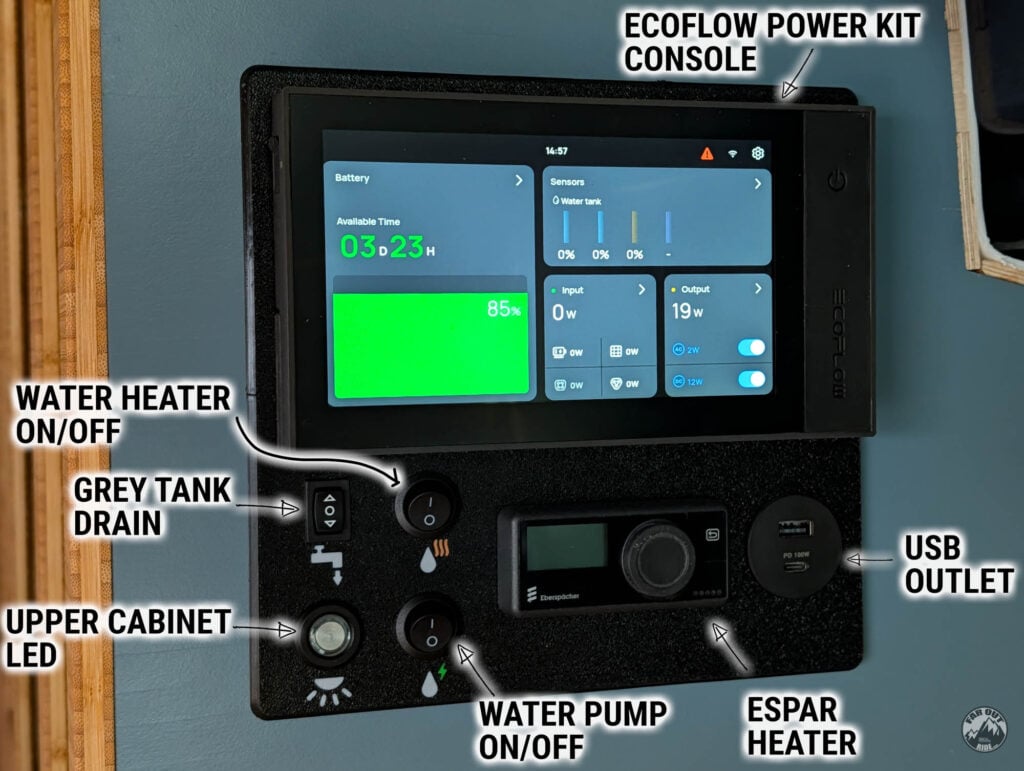
The console is part of our “Dashboard”, which is displayed in the main living area. It’s installed on the front face of our Bedroom Cubbies Cabinet (still a work in progress):
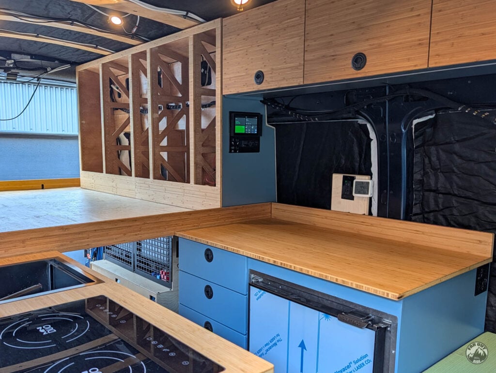
The dashboard is 3D printed and still in progress (we’ll remove the USB outlet, and add a switch for Starlink, and what else?), but we installed it temporarily so we can use it now.
- Water Heater ON/OFF:
- Grey Tank Drain:
- Upper Cabinet LED:
- Water Pump ON/OFF
- Espar Heater Control
- USB Outlet
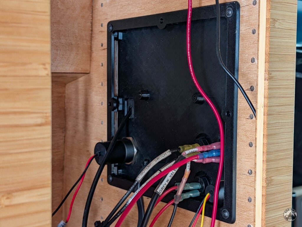
The back of the dashboard is still a mess, will make it tidy later!
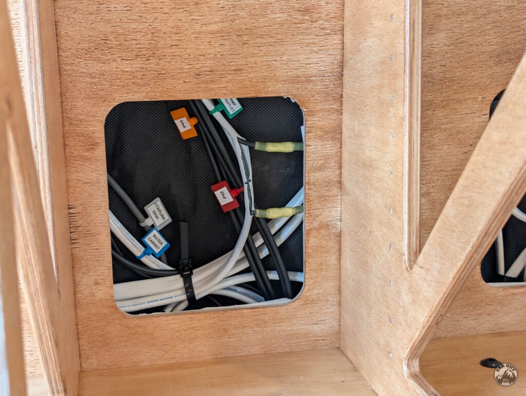
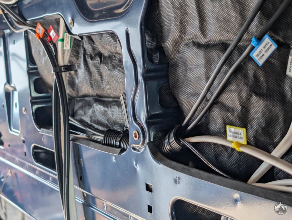
Cables Management
We left a 1.125in gap behind the batteries to hide the battery cables. We also designed 3D Printed Cable Management Clips to prevent vibration-related movement (chafing) and to mount the RJ45 Splitter. AND because we have a thing for cable management ☺️


Connections and Wiring
The EcoFlow Power Kit includes most cables, which are pre-wired (the connectors already installed so that you can skip the cut/crimp/heat shrink!).
Cables included with the Power Kit (GEN2):
- DC OUT (Power Hub -> Distribution Panel). 3 AWG.
- AC OUT (Power Hub -> Distribution Panel). 6 AWG.
- ALT IN (Alternator Power -> Power Hub). 3 AWG.
- AC IN (Shore Power Inlet -> Power Hub). 6 AWG.
- PV IN (Solar Power -> Power Hub).
- BATTERY (Battery(ies) -> Power Hub).
- Communication Ethernet Cables (Power Hub, Distribution Panel, Console, Power Link).
Cables NOT included with the Power Kit:
- DC LOADS (fan, fridge, lights, water pump, etc.).
- AC LOADS (Induction, water heater, oven, 120V outlets, etc.).
To Use Ferrules Or Not
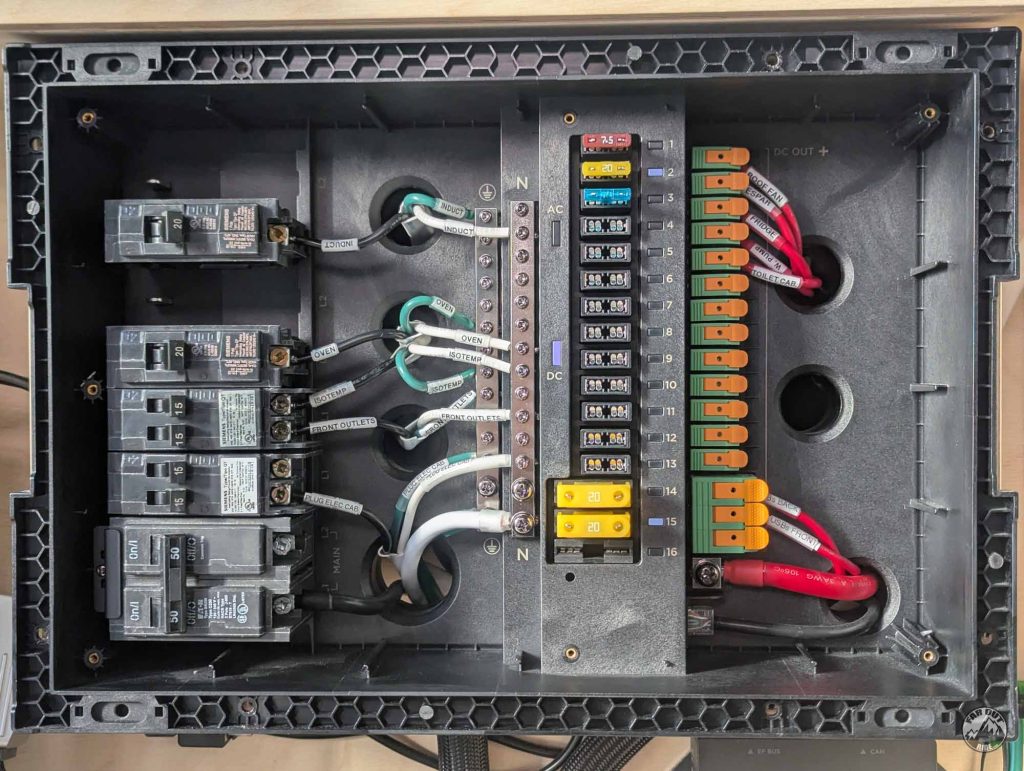
Most terminals on the EcoFlow 30/50A Distribution Panel (GEN2) are set-screw type, except for the DC + loads bus bar which utilizes lever-nut type):


The connection relies on a screw that bears directly into the wire strands. We’re not super-fans of this, because there is a risk of damaging the finely stranded wires. This could result in a higher resistance point, voltage drop, or wire damage (vibration-induced).
Some set-screw terminals feature a pressure plate to distribute the load over a larger surface. That’s not the case here; so we prefer to use ferrules to achieve load distribution. This is acceptable PER ABYC (more info here).
Note that the DC + loads bus bar utilizes lever-nut type terminals; do not use ferrules on those.
1. Strip the wire and insert a non-insulated ferrule (cleaner install and more compact than insulated ones):

2. Use a ferrule crimp tool to secure the ferrule:

3. We like to add adhesive-activated heat shrink tubing with a heat gun:

Wire Labeling
Soon, you’ll have a spaghetti of wires in your van.
Label. Your. Wires.
Future you will thank you!
We tried different methods and only one provided clear, permanent labeling:
1. Use a P-Touch (this one is Bluetooth; type and print from your phone) with 6mm label to create a label:

2. Stick the label to the cable:

3. Slide clear heat shrink over the label and set with a heat gun:

The method above is quite time consuming though, and at some point we started using Nylon Zip Tie Tags with 12mm P-Touch tape:
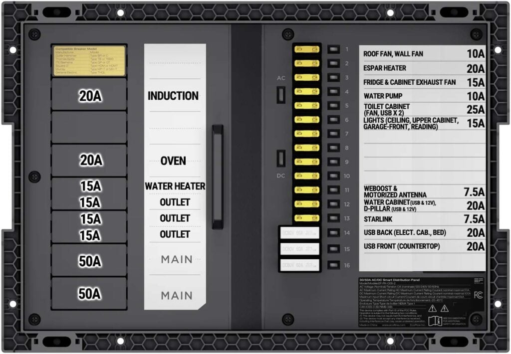
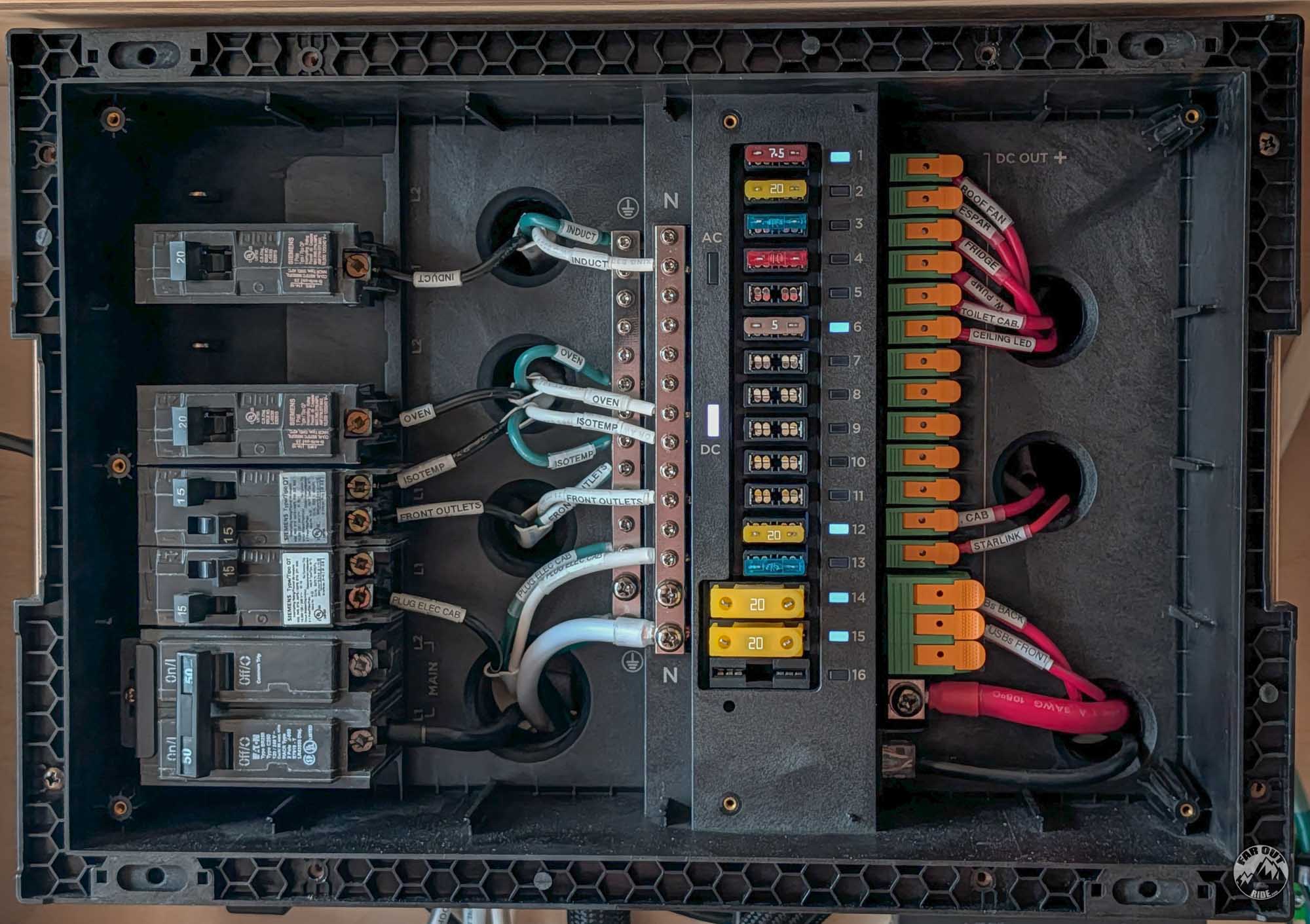
30/50A Distribution Panel (Gen2)
DC Out Cable
(Included)
Connect the DC OUT cable positive (red) to the terminal labeled as “DC IN +” on the front of the Distribution Panel:

Connect the DC OUT cable negative (black) to the terminal labeled as “DC IN -” on the right side of the Distribution Panel:

Connect the DC OUT cable to the right side of the Power Hub:

Shortening the Length of the DC OUT Cable
We decided to shorten the DC OUT cable to keep things tidy. We added ferrules to the positive and negative wires (3 AWG). Because our ferrule crimp tool can’t crimp 3 AWG cables, we used the Temco Hydraulic Crimper with “6 AWG+” size (using 3 AWG size wouldn’t work, because ferrules are much thinner than lugs).

AC OUT Cable
(Included)
First, you must buy the Main Circuit Breaker (2-pole). EcoFlow supports the model listed below (more models in the manual):

Install the Main Circuit Breaker on the lower-left side of the Distribution Panel (identified as “MAIN L1 L2”):
Before:

Breaker in place:

Lock the main circuit breaker using the provided hold-down bracket:

- Connect “L” (black) wire to L1 of the main breaker;
- Connect “N” (white) to the neutral terminal;
- Connect “PE” (green) to the ground terminal:

Connect the AC OUT cable to the right side of the Power Hub:

Shortening the Length of the AC OUT Cable
It is totally acceptable to keep the full length of the AC OUT cable. However, we decided to shorten it to keep things tidy:
The three wires (6 AWG) are encapsulated in protective sheathing and a thick rubber conduit. You will have to remove the rubber conduit (see next photo) and install ferrules:

To prevent damage to the inner wires’ insulation, use a carpenter’s knife to cut the rubber conduit along its length, starting at the extremity. Then work your way up. This way, you can see the depth of your cut. Do not go all the way through; aim for 90% depth and use force to tear the remaining depth. Again, this is all to prevent damaging the inner wire’s insulation.

Alternator
Accessing Alternator Power
How to tap into alternator power varies with brand/model/variant. Ensure to follow your owner’s manual!
- Ford Transit: BEMM.
- Mercedes Sprinter: BEG.
- Ram ProMaster: Body Builder’s Guide.
ALT IN Positive Connection
(Included, but we changed the terminal lug)
Our Ford Transit 2021 has two CCP (Customer Connection Points) connections, located on the driver-side pedestal:
- CCP1 (bottom): 60A fuse. M5 stud and nut.
- CCP2 (top): 175A fuse. M8 stud and nut.
The EcoFlow Power Kit GEN2 can charge up to 100A (12V alternator) if using PV1 input. We can therefore connect to the Transit CCP2. The CCP2 is fused at 175A, but we are adding a BlueSea 120A breaker to protect the EcoFlow ALT IN wire (3 AWG) and to act as a manual ON/OFF switch. The BlueSea 285 circuit breakers utilize 1/4″ studs.
Fuses and breakers are the weakest link in an electrical circuit. They are meant to protect the wires when the current goes higher than what they can handle. Learn more: Electrical System Guide | Overcurrent Protection
1. On the ALT IN cable, we kept the OEM lug (5/16″ or M8) on the negative wire, but installed a 1/4″ lug on the positive wire:

2. We prepared the cable connecting the breaker (1/4″ stud) to the Ford Transit CCP2 (M8 stud). We cut a short section at the extremity of the ALT IN cable (3 AWG):

3. We prewired the BlueSea 285 Breaker (120A):

4. At last, we connected the wire to the Ford Transit CCP2 (M8 threads) and installed the breaker in its enclosure (secured to the seat pedestal with VHB tape):
ALT IN Negative Connection
(Included, no change)
First things first, BEMM Section 4.5.3:
High electrical loads should also be grounded directly to the vehicle body and not the negative battery terminal. Connecting to the negative battery terminal will bypass the BMS and affect the correct assessment of the battery state of charge. Refer to BMS section in this manual.
The Ford Transit BEMM recommends the following ground points, and these should be used if possible:
That being said, the BEMM does not mention if these ground points are suited for large current or not… some of them don’t seem suited for large current… We will therefore use this wildcard that seems to have appeared in the 2025 BEMM (Section 4.25, page 222):
If a new grounding point is required, avoid placing it in a wet area, especially for high current grounds. Ground connections should be routed back close to the location of the +12V supply. This helps to reduce the electromagnetic field particularly generated by inrush current and improve electromagnetic compatibility.
We will create a new grounding point not far from the +12V supply (the van’s battery), just behind the driver seat:
1. We drilled a hole and, using a wire brush, we removed the paint on the surface mating with the terminal lug (this is a high-current application, we want as much surface contact as possible; do NOT rely on bolt’s threads for conduction!):

2. We inserted an M8-1.25 x 16mm serrated flanged bolt (stainless), applied dielectric grease on the bare metal (to prevent corrosion), then added the ALT IN negative wire, and a M8 serrated nut (stainless). Do not use a washer between the van chassis and terminal lug:

3. Another angle:

4. Connect the ALT IN cable into the EcoFlow Power Hub:

ALT IN Cable Protection
All wires must be protected from abrasion, cuts, and chafing; this is especially true in a mobile application subject to vibration! Use grommets on sharp edges, and secure the cables in split-loom tubing. Got a 3D printer? Sweet! We designed grommets (printed in TPU) to protect against sharp edges through the C-Pillar:


Shore Power
Choosing between 30A or 15A Inlet
(Both the GEN1 or GEN2 Power Hubs can accept 30A AC INPUT)
30A
CHARGE POWER: 3000W.
CHARGE TIME: 20 minutes for each 1kWh.
(e.g. 100 minutes for 5kWh).
Regular house outlets are rated for up to 15A (20A sometimes). To enable 30A charging, you must visit campgrounds, State and National Parks, travel centers, etc (though not all provide 30A shore power).
15A

CHARGE POWER: 1500W.
CHARGE TIME: 40 minutes for each 1kWh.
(e.g. 200 minutes for 5kWh).
You can install a 15A inlet if you never plan on charging 30A. That’s most likely our situation, but we still installed a 30A inlet just in case… See below.
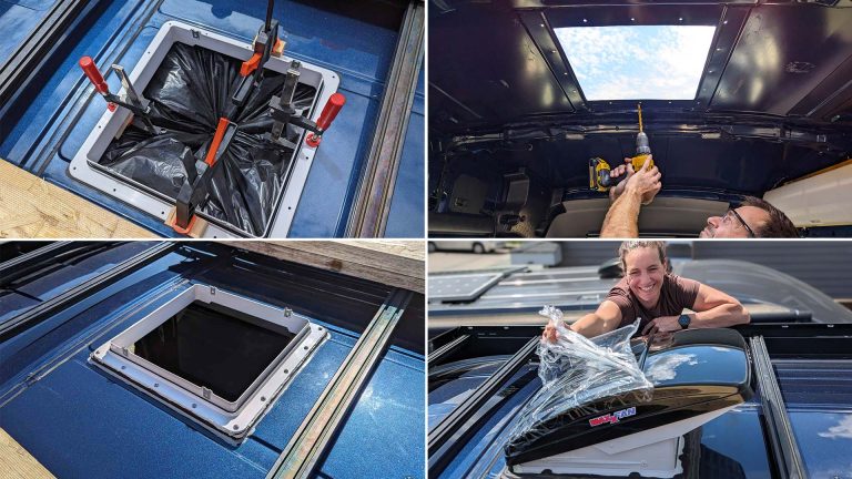
1. Route the AC IN cable (included) into the existing openings near the Transit D-Pillar:

2. Route the AC IN cable through the existing cutout under the D-Pillar. No drilling required!

3. Route the AC IN cable through the Shore Power Entry Box and the Marinco inlet’s safety enclosure:

4. Insert the gasket and connect the wires into the 30A Marinco Inlet:

5. Fasten the strain relief:

6. Fasten the Marinco Inlet into the Entry Box using the 4 included screws (it’s a TIGHT fit, not exactly easy, but doable!). Do NOT overtighten the screws; hand-tight to slightly compress the gasket, not more.
The wires should exit at the BOTTOM of the box, to create a drip loop (forces water to drip at the bottom, prevents water from entering the inlet):

7. Push the entry box into the D-Pillar cutout, one edge after the other:

8. Voilà, we made it!

9. You can use a 30A (female) to 15A (male) adapter to connect to a 15A “normal” house outlet. Like this one (Buy on Amazon):

10. This one (Buy on Amazon) has a much smaller footprint, I like it better:

11. Important! The EcoFlow Power Kit can charge up to 30A. Before connecting to a 15A house outlet, ensure to limit the AC input current to 15A to prevent blowing the fuse of the house outlet. This can be done via the smartphone App or the Console display.

Shortening the Length of the AC IN (Shore Power) Cable
It is totally acceptable to keep the full length of the AC IN cable. But if you decide to shorten it, be aware that removing the insulation without damaging the inner wire is quite difficult.
The three wires (3 AWG) are encapsulated in protective sheathing and a thick rubber conduit. High quality!

To prevent damage to the inner wires’ insulation, use a carpenter’s knife to cut the rubber conduit along its length, starting at the extremity. Then work your way up. This way, you can see the depth of your cut. Do not go all the way through; aim for 90% depth and use force to tear the remaining depth. Again, this is all to prevent damaging the inner wire’s insulation.
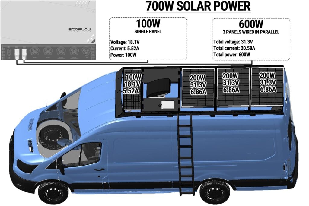
Solar Panels
Solar panels of any brand can be connected in series (same current, voltage is added) or parallel (same voltage, current is added). Remember that mixing solar panels (different brands/specs) should be avoided if possible (refer to: faroutride.com/electrical-system/#mixing-solar-panels). Solar panels can be connected to the PV Input 1, 2, or 3 of the Power Hub, as long as these specifications are met:
GEN 1 Power Hub
- PV Input 1: 15-60V | 30A.
- PV Input 2: 15-60V | 30A.
- PV Input 3: 15-60V | 30A.
GEN 2 Power Hub
- PV Input 1: 13-60V | 100A.
- PV Input 2: 13-60V | 30A.
- PV Input 3: 13-60V | 30A.
We reserved PV Input 1 for alternator charging, because it allows charging at a high rate (100A). We are left with PV 2 and PV 3 for solar:
Installing the solar panels involves the EcoFlow Power Kit, as well as the roof rack. We packaged it all together in this guide:

Batteries
You can connect up to 3 batteries directly to the Power Hub. To connect more batteries, use a Power Dock (up to 9 batteries are supported!):

Remove the rubber cover on both the Power Hub and the battery:

Connect the EcoFlow’s Battery Cable to the battery and the Power Hub (Battery 1 / 2 / 3 ports). No wiring required, nice!

Grounds
The EcoFlow Power Kit features a floating ground separated from the chassis ground. While grounding is not mandatory in mobile applications, it provides a return path if the main negative path fails.
1. We connected a 6 AWG wire (Per EcoFlow owner’s manual) to the ground stud on the right side of the Power Hub and the Distribution Panel. We “extracted” the green wire from the AC OUT cable that we shortened:

2. We created a new ground point (per BEMM) by removing the paint (with a wire brush attached to a Dremel), and secured the ground wires with an M8 serrated bolt and nut (stainless):

3. Close-up on the chassis ground point, with cables coming from the Power Hub and the Distribution Panel:

Communication
The EcoFlow Power Kit components “talk” to each other via Ethernet cables.
- Connect one Ethernet cable from the Power Hub to the Console (display).
- Connect the other Ethernet cable from the Power Hub to the Distribution Panel.
OR, if you have a Power Link, connect the other Ethernet cable from the Power Hub to an RJ45 Splitter (Buy on Amazon), then to the Distribution Panel and the Power Link. Then add the Termination Resistor (included) into the Power Link:


Shortening the Ethernet Communication Cables
We shortened the Ethernet communication cables to keep things organized. If you decide to do the same, get an RJ45 Ethernet Crimp Tool Kit. Several YouTube Videos show how to do this.


Temperature Sensors
Resistive-type temperature sensors are allowed. To add a sensor:
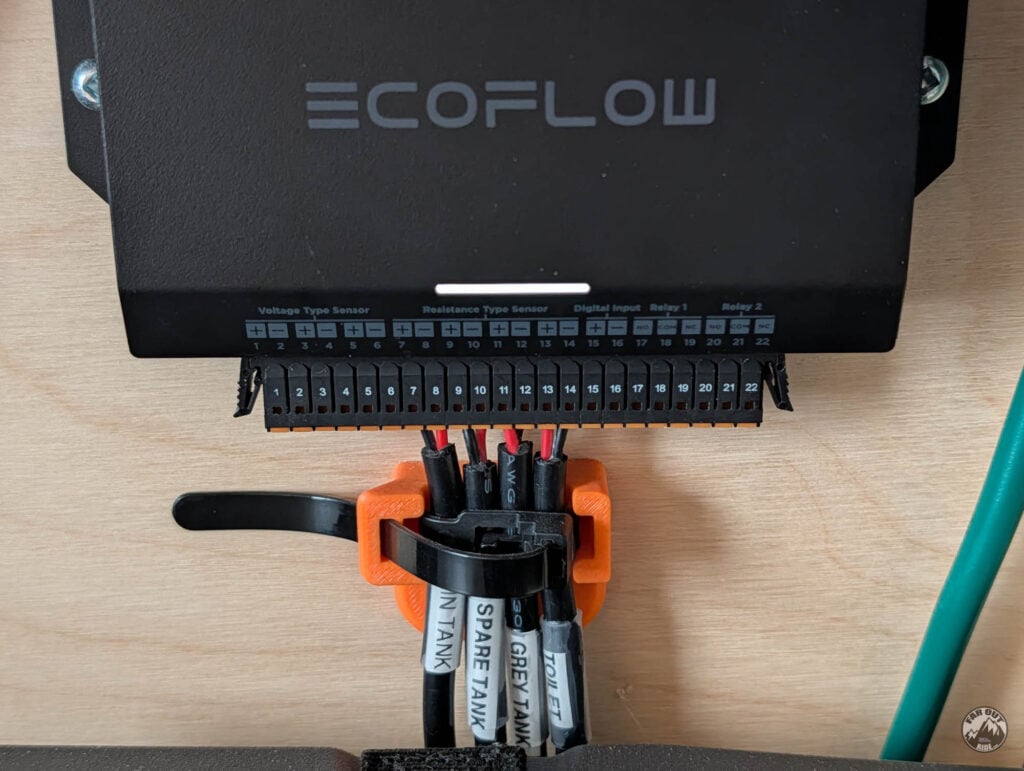
1. Push the orange tab to open the terminal, then insert the two wires into the terminal block (terminal 7/8, 9/10, 11/12, 13/14):

2. Push the terminal block into the EcoFlow Power Link:

3. Click on “Add sensor” and fill all the inputs:

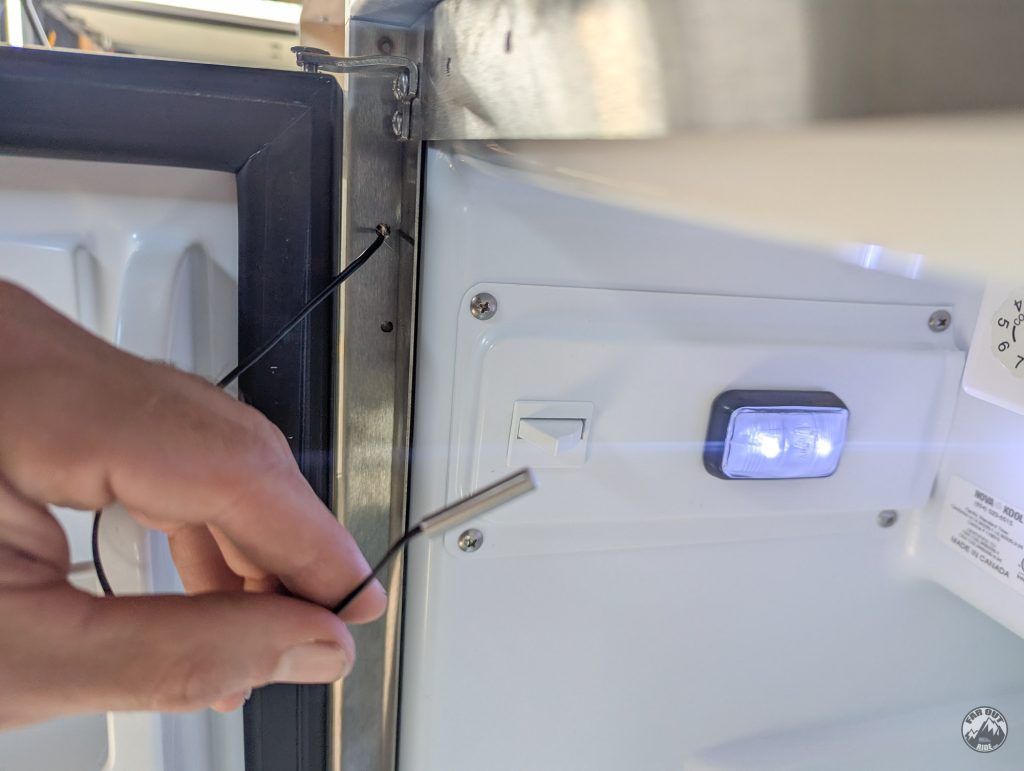
So far, we have added temperature sensors to the fridge and to the van interior:
Here’s the fridge sensor. We documented the wire routing in the Fridge Cabinet Page (faroutride.com/fridge-cabinet/#temp-monitor):
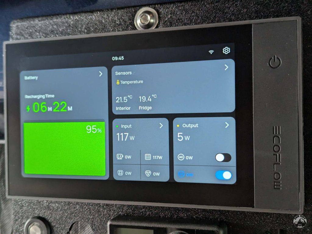
This is how the temperature sensors are displayed on the console:
Tank Level Sensors
Resistive-type tank level sensors are allowed.
We use KUS SSS Fuel & Water Level Sensors in all our tanks:
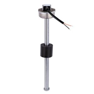
The tanks we chose feature a 1.5″ NPT port, so the KUS sensor simply screws into the tank, easy!
We wired the tank sensors into the Power Link (we decided to use Switchbot Wireless Sensors for temperature/humidity monitoring instead):
Tank level on the console (all tanks are currently empty…):
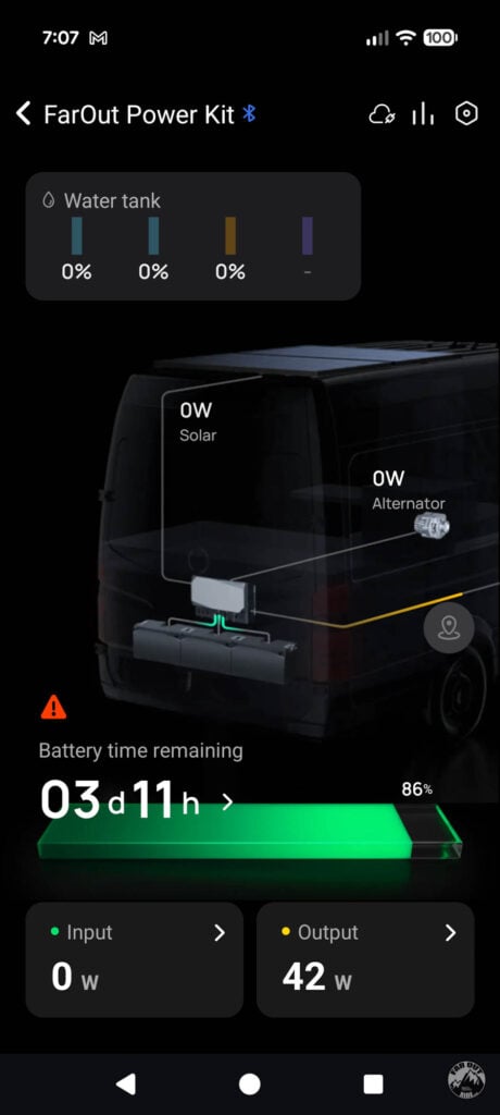
Tank level on the app:
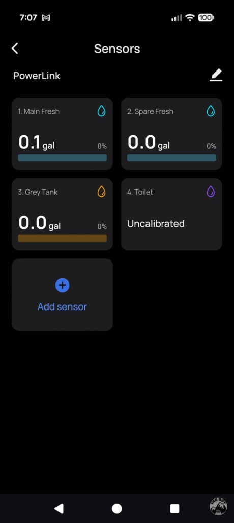
Sensors menu:
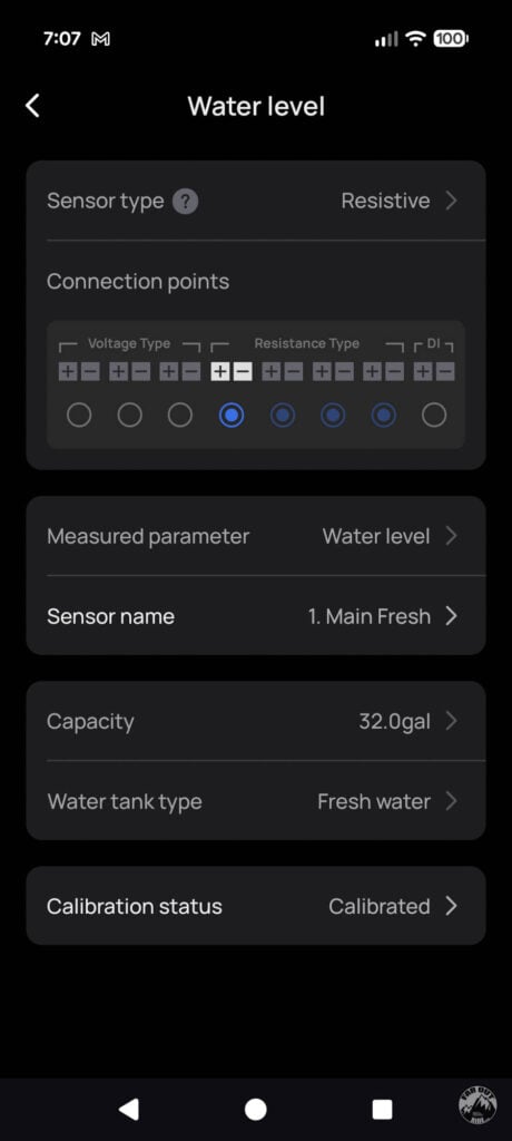
Clicking on a single sensor:
Calibration menu:
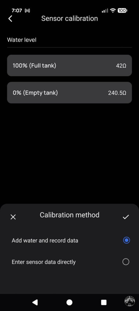
Tank Level Calibration
- Park the van level.
- Fill your tank, and record the value for 100% (full tank).
- If your tank is irregularly shaped, dump water into a graduated container. Record the value. Repeat.*
- Empty your tank, and record the value for 0% (empty tank).
* For a perfectly rectangular tank, 2 calibration points are enough (100% and 0%).
** You can also go from empty to full (instead of full to empty), but adding a known volume of water is harder than removing a known volume, unless you can gravity-fill your tank…
Settings
Below is not an exhaustive list, we only showcase the settings we believe are more important!
Here is how to access the General, Batteries, Input, Output, and Sensors settings from your Dashboard in the smartphone App:

General Settings
The timeout settings allow to conserve energy:
- System timeout: Shuts down the entire system after a specified time, if the system is idle with no loads or user interaction.
- AC timeout: Shuts down the AC loads after a specified time, if total loads are below the specified threshold.
- DC timeout: Shuts down the DC loads after a specified time, if total loads are below the specified threshold.

Batteries Settings
The discharge and charge limit can be specified:
- Discharge limit: The battery bank won’t discharge below this threshold.
- Charge limit: The battery bank won’t charge above this threshold.
Battery life:
- To obtain longer battery life, it is recommended to set the discharge limit to 20% (or more).
Long-term storage:
- To maximize the lifespan of the battery bank during long-term storage, store at 60% SOC.
- It is recommended to discharge to 30% and charge to 60% every 3 months.

Input Settings
- AC INPUT CURRENT: Useful to prevent blowing a fuse (e.g. set to 15A on a “regular” home 120V 15A outlet).
- ALTERNATOR CHARGING CURRENT: Useful to prevent overworking the alternator. As a *general* rule of thumb, set to half the total capacity of your alternator.
- CHARGE WHILE IDLING: We turn it OFF when we use the van occasionally for commute only. We turn it ON on long road trips, while the starter battery gets plenty of charge time.
- CHARGE THE STARTER BATTERY: To charge the starter battery from your Power Kit Battery Bank. This could be used in an emergency when your starter battery is depleted. Note that this is NOT a jumpstart; it will take a while to recharge the starter battery (compared to a jumpstart, which is “instantaneous”).

Output Settings
- DC OUTPUT VOLTAGE: Can be set to 12V or 24V. All your DC LOADS should accept the specified voltage. Choose during initial setup of the Power Kit and DO NOT CHANGE AFTER to prevent damaging your DC loads!

Sensors Settings
- Not much to mention, except press and hold a sensor to DELETE it (that one was hard to find)!

DC & AC Loads: Complete List
Here are the DC Loads and AC Loads we plan on having (subject to change!), vs what we have so far (still a work in progress, but we’re getting there!):
DC Loads
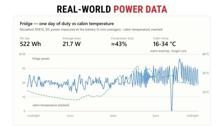
Fridge
Specs:
- Brand/Model: NovaKool R5810
- Fuse: 15A @12V or 7.5A @24V
- Power draw (when running): 48W
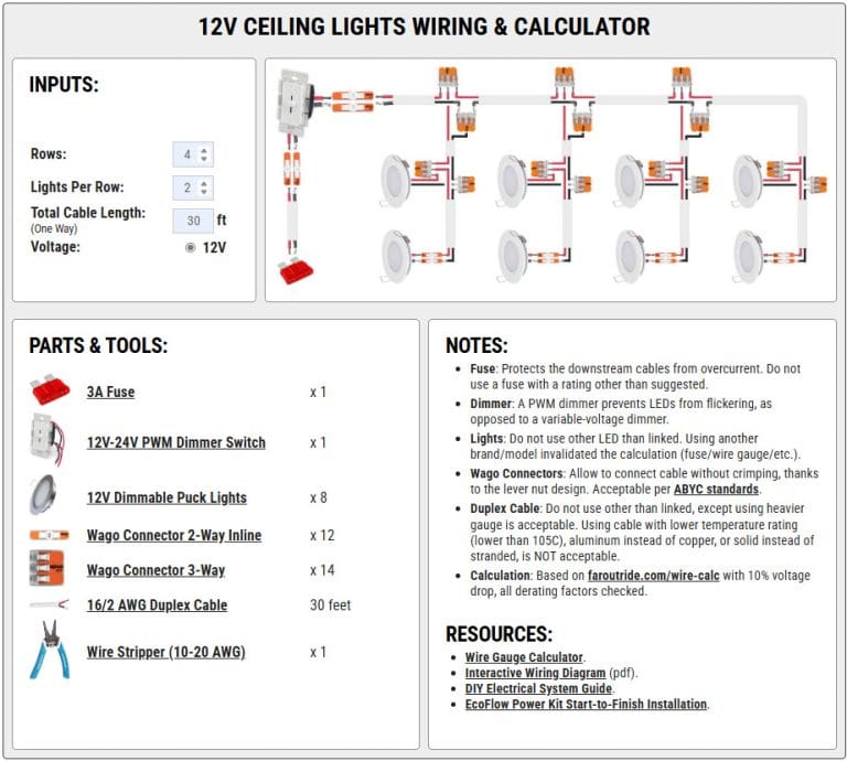
Ceiling Lights
Specs:
- Brand/Model: Acegoo 2.75″ Recessed LED (dimmable)
- Fuse: Use our calculator (link below)
- Power draw: 3W each (max intensity)
Upper Cabinet Recessed Light
Specs:
- Brand/Model: COB LED Strip
- Power draw: 9W/meter (max intensity)

Garage Lights
coming soon
Roof Fan
Specs:
- Brand/Model: Maxxair Maxxfan 6200k
- Fuse: 7.5A (12V)
- Power draw:
| Speed | Power (Watt) | Current @ 12V (Amp) |
|---|---|---|
| 1 | 2.4 | 0.2 |
| 2 | 3.6 | 0.3 |
| 3 | 4.8 | 0.4 |
| 4 | 7.2 | 0.6 |
| 5 | 10.8 | 0.9 |
| 6 | 14.4 | 1.2 |
| 7 | 19.2 | 1.6 |
| 8 | 24 | 2.0 |
| 9 | 31.2 | 2.6 |
| 10 | 44.4 | 3.7 |
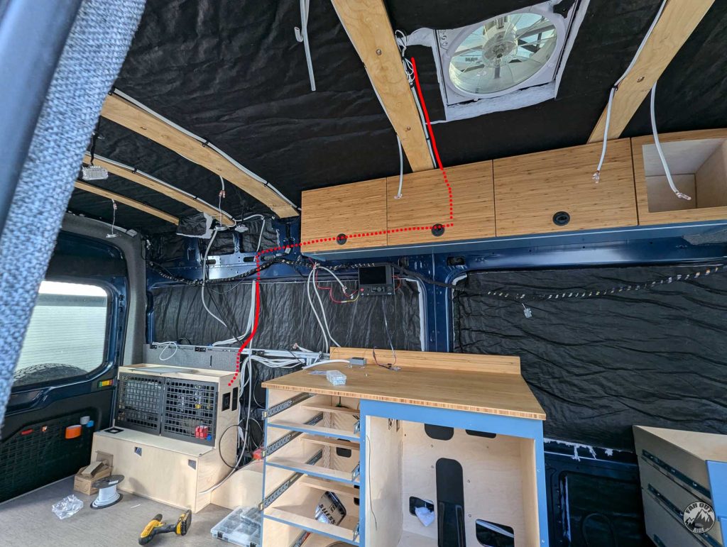
Wiring:
- The Maxxfan is wired to the duplex cable with Wago 221-2401 connectors.
- The duplex cable is routed through Cable Clamps that are screwed to the frame (screwed to the vertical edge of the frame, so the clamp/wire does not interfere with the ceiling planks that we will install later).
- The cable is then routed inside the van wall all the way to the electrical cabinet.
Wall Fan
coming soon
Water Pump
Specs:
- Brand/Model: Shurflo Revolution 4008
- Fuse: 10A @12V
- Power draw: 85W when running

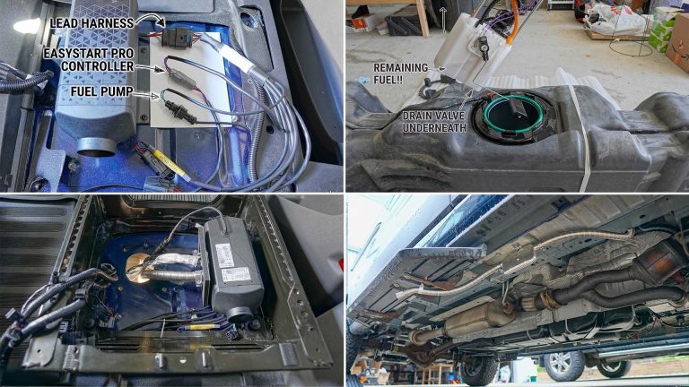
Espar Gasoline Heater
Specs:
- Brand/Model: Espar AS3-B2L
- Fuse: 20A @12V
- Power draw: 11-26W when running / ~80W at startup
USB Outlets
Specs:
- Brand/Model: Acegoo 118W 12V USB-C and USB-A
Installation:
coming soon
Composting Toilet
coming soon
Air Conditioner
We don’t personally have an air conditioner in our van, but here’s the relevant information.
Another selling point of the EcoFlow Power Kit is that 48V Air Conditioners can be easily added. Use the 48-Volt Air Conditioner EcoFlow Cable and connect it to any of the three battery ports on the Power Hub GEN1, or to the 48V Port on the Power Hub GEN2.
GEN 1 Power Hub
- Battery Port (x3): 40-60V | 100A MAX.
GEN 2 Power Hub
- DC Output 48V: 40-57.6V | 55A | 3,168W MAX.

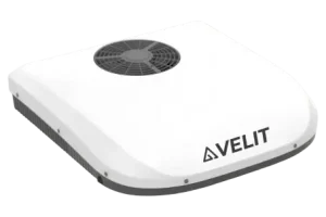
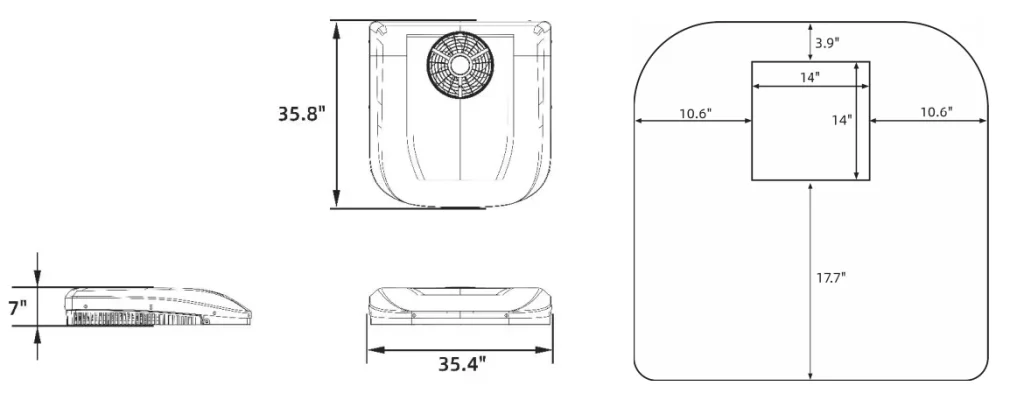
Velit 2000R Mini Rooftop A/C 48V
7500BTU | Fits Standard 14″ x 14″ Cutout


Velit 3000R Rooftop A/C 48V
12,000BTU | Fits Standard 14″ x 14″ Cutout
AC Loads
Water Heater
Specs:
- Brand/Model: Isotemp SPA 15L
- Breaker: 15A @120V
- Power draw: 750W when heating.
Induction Cooktop
Specs:
- Brand/Model: True Induction Mini Duo
- Breaker: 20A @120V
- Power draw: 1800W max

Oven
Specs:
- Brand/Model: Breville Smart Oven Pro
- Breaker: 20A @120V
- Power draw: 1800W max
e-Bikes
Specs:
Santa Cruz Bullit:
- Battery capacity: 600Wh
- Motor: Bosch CX
- Charger: Bosch 4A Standard Charger (BPC3410)
- Peak draw: 190W (~4.5h full charge)
- Single charge consumption: ~670Wh
Transition Repeater EP8:
- Battery capacity: 630Wh
- Motor: Shimano EP8
- Charger:
- Standard (EC-6002): 90W Peak (~8h full charge)
- Fast (EC-E8004): 190W Peak (~4.8h full charge)
- Single charge consumption: ~700Wh
Charge Graph
120V Outlets
GFCI vs Non-GFCI
GFCI outlets protect from electrical shock by interrupting the circuit if an energy leak is detected. In homes, the NEC requires GFCI outlets in wet or damp areas (basements, bathrooms, kitchen countertop, etc.).
What about campervans? Is the entire van considered “damp”? Should we use GFCI outlets? Well, here’s an easy answer:
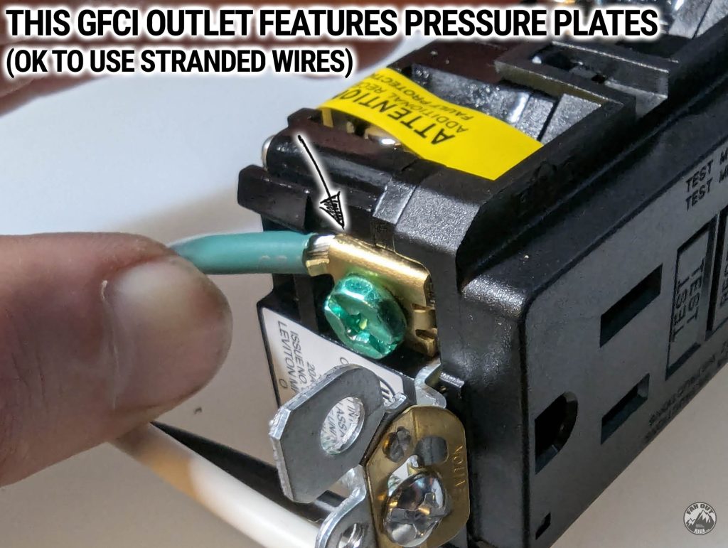
Most 120V outlets only accept solid wire, which shouldn’t be used in vans/RVs/boats. However, we found that this GFCI outlet is designed to accept stranded wires, thanks to the pressure plate terminals.
Electrical Boxes
Electrical boxes (aka junction boxes) enclose the outlet and its connections, helping to protect against short circuits. We like to use PVC Old Work Box (or “remodeling box”) in our van, because they’re simple to install in a rectangular cutout:


120V Outlet Wiring and Installation
Below is how we wire the 120V Leviton Slim GFCI outlet into a Shallow PVC “Old” electrical box. This specific case involves wiring our Induction Cooktop, so we are using a Leviton 20A Slim Outlet, a “shallow” electrical box, and 12 AWG Triplex Cable.
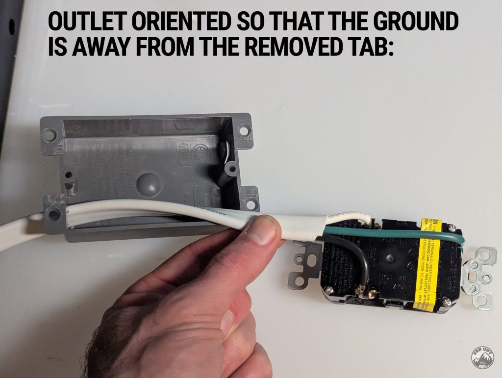
1. Remove a tab from the electrical box:

2. Route the cable through the junction box. If using a shallow junction box, orient the outlet with the ground (green) away from the removed tab. Here’s an “after” photo to illustrate that:
3. Strip the green cable and install it into the pressure plate with the green screw:
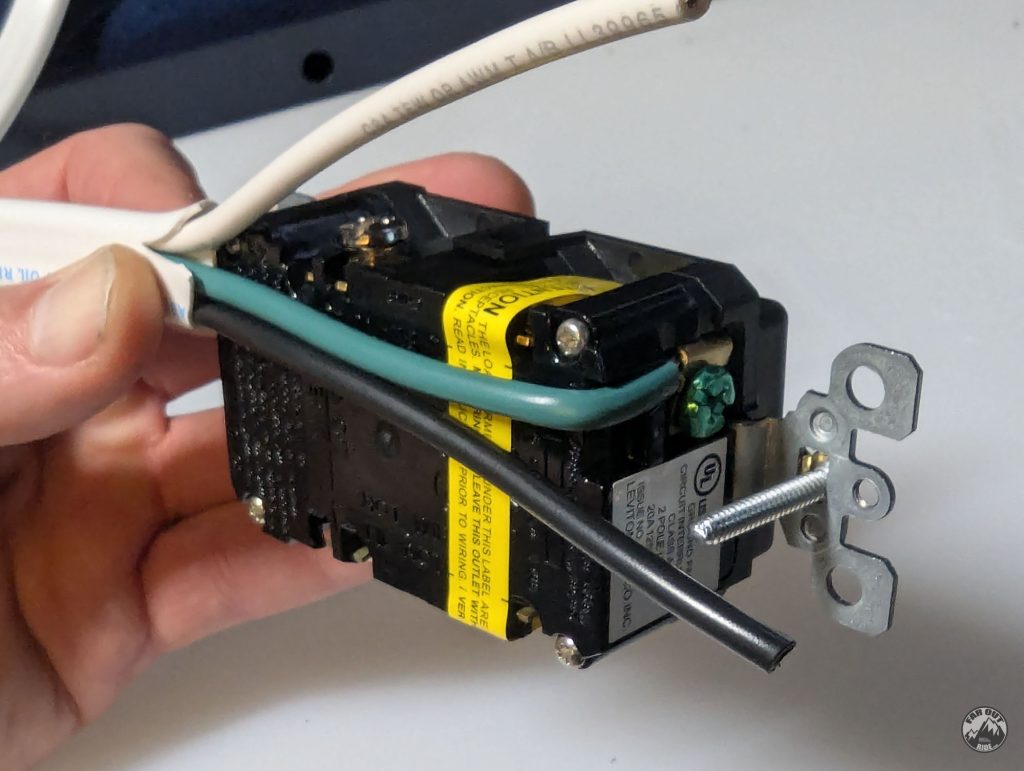
4. Shorten the white wire, strip, and install it into the pressure plate labeled as “white wire”:

5. Shorten the black wire, strip, and install it into the pressure plate labeled as “black wire”:
Note how this arrangement is neat and “flat”, which is essential to fit into the shallow electrical box!
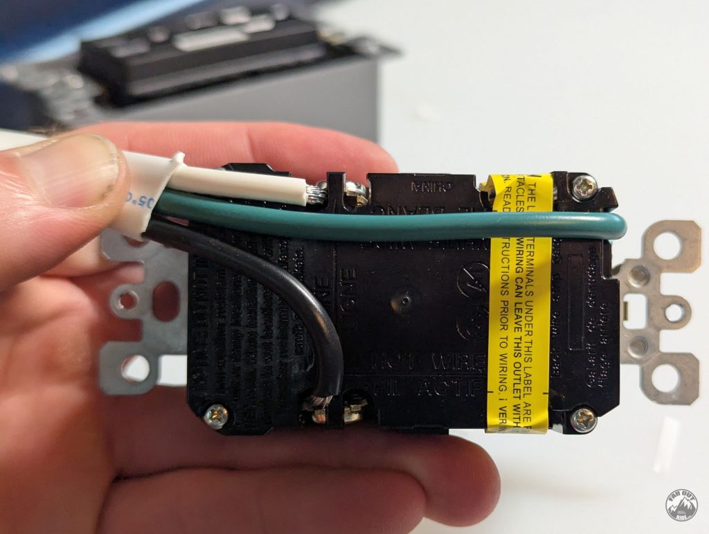
6. Use the screws provided with the outlet and fasten it into the electrical box:
The outlet presses against the wires, providing strain relief (prevents pulling the cable out).

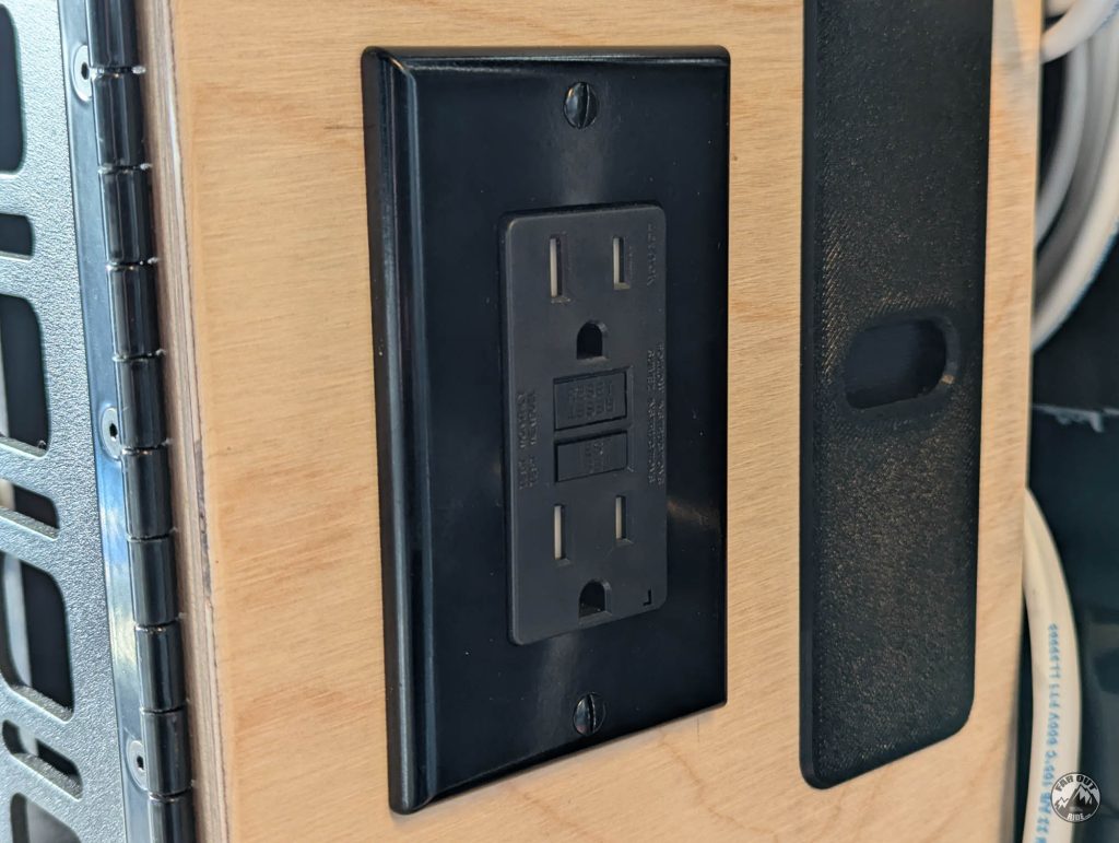
7. Install the electrical box into the cabinet (cutout size: 93mmx63mm for this electrical box):
(photo coming soon)
8. Install the wall plate:
9. Connect the 120V outlet to the AC Distribution Panel (as documented in Distribution section):
Real-World Data
After a few trips, data is starting to come in! The following post gathers real-world consumption data for the appliances listed above. It’s a living post — we’ll update it as we go:
After a Year: Would We Buy It Again?
WHAT WE LIKE
- Install measured in hours, not days.
- One console and app for the entire system.
- 48V architecture keeps cables small and routing easy.
- Single vendor for support and warranty.
- Expandable with a second 5kWh battery.
WHAT WE DON’T LIKE
- Proprietary ecosystem — you’re married to EcoFlow.
- “Clicking” sounds from the solar relays, early in the morning or in low-light conditions.
Net: a year in, it’s done everything we’ve asked of it. Still deciding between plug-and-play and DIY? That’s exactly what we cover in EcoFlow Power Kit vs Victron (Decision Time!).
FarOutVan 2 Electrical System
EcoFlow Power Kit 5kVA Gen2 with Console — it’s been on and running for over a year now: induction cooktop, oven, water heater, fridge, Starlink, charging our two e-bikes, and more. Fresh & grey water tank levels are monitored in the console.
If it’s the right fit for your build: 10% off with code FAROUTRIDE10 at Campervan-HQ (USA), or 5% off with code FOR5EF at TecVan (Canada, Gen1). With our code, this is usually cheaper than buying straight from EcoFlow. These folks know vans and are very responsive. Using our links/codes supports FarOutRide at no extra cost to you — thanks!


Thanks so much for all the info, super helpful! Quick questions, does the wire gauge calculator apply to 110V/120V outlets as well? And what size wire gauge are you using for your 15 amp/120V and 20 amp/120V outlets? Thanks!
The calculator is for 12/24/36/48V:
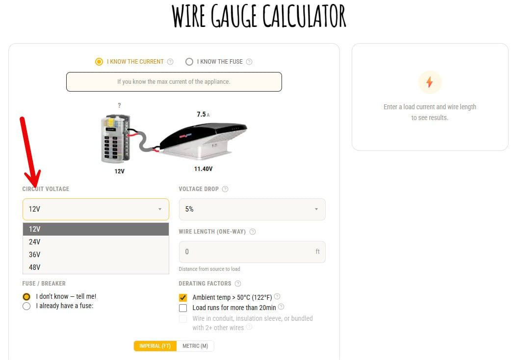
For 120V we ordered a 100ft roll of 12 AWG Triplex cable and use that for all our outlets. You can use 12 AWG triplex cable up to 50ft per run, per https://faroutride.com/ecoflow-install/#ac-outlets.
Thanks for the reply
Hi Antoine. I purchased your Blue Sea 285 series box/cover and installed it in my 2026 Transit 350 today. While wiring up my breaker to CCP2, I again looked at the pictures in your installation guide and noticed that it appears that you have your cable from CCP2 connected to the Blue Sea 285’s AUX post and your Alt In cable connected to the BAT post. I think that is backwards and you may want to flip your breaker 180 degrees and reconnect the CCP2 cable to BAT and Alt IN to AUX. From what I understand, the Blue Sea 285 breakers are directional and the LINE/HOT cable should be connected to the BAT post and the LOAD to the AUX post. Hope that’s of help.
Thanks again for your awesome guides and great custom made products! I’m using many of them in my build.
Hi!
The Blue Sea 285 are thermal breakers, and therefore are non-directional.
It’s a good idea to follow the convention, but wiring them in reverse won’t affect the function.
Thanks for the heads up, and let me know if I’m missing anything here 😉
That’s good to know. Thanks for the thorough explanation and quick response!
This is a test to check if notifications are working.
test yo yoasdlkfjal;sh fkajshd fklajshd flkasgd fgsdfsf
This is a test to check if notifications are working.
Antoine thank you for all the great content you provide! I was thinking of buying this kit, but it appears to be twice the price from when you purchased it. Is this correct?
I just had a quick look and I don’t see a price increase… Maybe you are comparing the GEN1 with the GEN2?
GEN 1 is cheaper, and it’s the one we use in our comparison (https://faroutride.com/ecoflow-vs-victron/).
I am purchasing an Ecoflow kit and need help with my wiring diagram. I am considering purchasing the PDF you created, and want to ensure that it is updated to include the Ecoflow product on the PDF before buying. Thank you!
The wiring diagram is for DIY electrical system; it does not cover the EcoFlow.
But that’s the great thing about the EcoFlow… you don’t need a diagram for the core components 🙂
For your appliances, you can calculate your wire sizes with this calculator: https://faroutride.com/wire-calc/
Cheers,
Antoine
This is a test to check if notifications are working.