After some trial-and-error we finally found what (we think) are the perfect recessed ceiling LED lights! The first LEDs we ordered were WAY too bright as the glass was clear instead of frosted. Even with a dimmer, the light was shocking for the eye. Then we stumbled on the Acegoo LED lights…
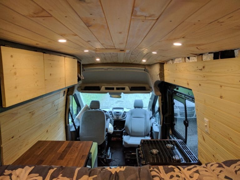
We installed 10 Acegoo Warm-White LEDs: in terms of lumens, 6-8 lights should be enough. We installed 10 in order to get a more uniform source of lighting (so when an overhead storage door is opened, we’re still getting light from somewhere).
The LED lights are operated with a dual zone dimmer; the bedroom zone has 4 lights, and the kitchen zone has 6 lights.
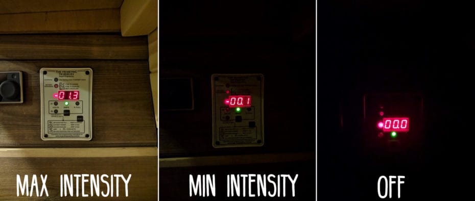
The 10 lights draw 1.3 amps total at 100% intensity, 0.1 amp total at minimum intensity. For reference, we will set the intensity to 100% when washing dishes, being productive, etc. We will set the intensity to approximately 10% for quiet moments.
What We Like about the Acegoo LED Lights
- They are dimmable (with an appropriate LED dimmer, see below)
- The frosted glass produces a soft & diffused light
- The spring mechanism makes it very easy to install and remove the LED from the ceiling
What We Don’t Like …
Nothing to see here!
Models & Where to Buy
Disclosure: This post contains affiliate links, which means that if you click a product link and buy anything from the merchant (Amazon, eBay, etc.) we will receive a commission fee. The price you pay remains the same, affiliate link or not.


Dimmer
LEDs MUST be dimmed with an appropriate LED dimmer. If you’re in the market for a 12V one, good luck! They are either super expensive or super ugly. After countless hours of research, we found the perfect match for our great LEDs! It’s a two-zone dimmer, so we can control the bedroom/kitchen LEDs independently. The sliders feel great and hold in place as they should. The lights are off when the sliders are completely down:


Ford Transit Factory Ceiling Lights Removal
Installation
It doesn’t get easier than this…

Using a 2-3/8″ diameter hole saw (Buy on Amazon), we prepared the cutouts in the paneling:

To install the LEDs, pull-up the two springs and then the LEDs just “snap” into place (and can later be removed easily).
For the wood paneling installation write-up: https://faroutride.com/wood-paneling/

Electrical Wiring
The lights MUST be wired in parallel (series won’t work). Here is the wiring diagram:

(Note: to size your wires, please read: Electrical System Design)
Material shown in the sketch above:
- Fuse Box
- 3M SCOTCHLOK Quick Splice Wire Connector – Blue Gel – 14 AWG
- 3M SCOTCHLOK Quick Splice Wire Connector – Yellow – 12 AWG
To have solid and reliable electrical connections with different wire diameters (14 AWG vs 22 AWG), we used:
On LED side:

On live side:

Random pictures:


Voilà!

Runner Up
As mentioned in the introduction, we first ordered LEDs from Superbrightleds.com. Why didn’t we use them? Because they are, well… SUPER-BRIGHT! The clear glass will not diffuse the light, and we found this to be very irritating. Also, we prefer the spring mechanism of the Acegoo LEDs; we feel they will hold better and can be replaced more easily. Don’t get us wrong: the quality of the superbrightleds.com is just fine. In fact, we would certainly use them at a location where the light is not directly in our eyes (such as the cargo area). But because of the clear glass, we would not recommend them for a living area.

Conclusion
We’re stoked with our Acegoo lights/Dual-Zone-Dimmer combo! If we were to start over, we would go the exact same route!


Hello Isabelle and Antione,
Many thanks for your write-up as I am taking quite a few notes for my own Sprinter build-out. General question about wiring things like lights and fans, using the Maxxair fan as an example: the fan comes with 16 AWG wires from the unit’s circuit board. Per your wiring calculator (and the example you use on that page) you chose to use 12 AWG to wire it up to the Fuse Box/Battery Bank. If the maximum current cannot exceed that allowed by the 16 AWG wire, then what benefit comes from using a larger wire from the fuse box? With lights in parallel I can see why an individual branch (light) can be 22 AWG while the cable from the fuse box would need to be larger to allow for the current of multiple lights before they split off, but I don’t understand the fan example.
The wire size calculation takes in consideration the length of the wire (in order to minimize the voltage drop) and the wire ampacity (maximum current/amp the wire can safely carry). For your information, according to ABYC standards, 16 AWG can carry up to 25amps. That being said, the Maxxfan requires 5amps (from the installation guide), so the main factor here for determining the wire size is the length from the battery bank to the fan.
Could you just use two more scotchlok connectors where all four wires meet so that you only have two going into the switch instead of the four? Thanks
Question do you have a diagram for using the yeti goal zero 3000x I purchased the builder pack then decided to go with the yeti 3000 instead of multiple batteries as l can also use on construction sites and my home.
Sorry, we don’t have one at the moment.
Agreed, a wiring diagram centered around a Yeti wouldn’t go unappreciated. From what I can tell, they’re gaining popularity in the van conversion world. Also, thanks for the awesome resource that this site is. I’m copying many elements from your build that I don’t know that would have occurred to me otherwise, not to mention the immeasurable amount of time saved.
Hello,
Thanks for sharing! I purchased the WIring diagram and love it!
Quick question, on the install tutorial for the LEDs (above) it says you used 14 AWG wire. But the wiring calculator you mentioned to use says to use 16 AWG.. any reason you didn’t follow the calculator? Just curious I am about to buy the lights and wat to be sure to get the right wire too.
The correct wire gauge depends on the length of YOUR installation and how many LED you install (total amps). So input that into the calculator (length = positive + negative) and use the recommended wire gauge 🙂
Do I have to buy the 18-22 male disconnect and 14-16 female disconnect? I know you said for a more solid connection to use these which I totally understand but would it also work if I just used 14 to 14 wire connectors since the 18 on LEDs could fit in there and then I could crimp the 18 side extra hard in there so no looseness? I just have a ton of these connectors already and wanted to get your opinion on going this route.
Bonjour Antoine/Isabelle –
In your load calculation, you mention that the Acegoo lights draw 3W each, that you used 10 of them… but then your 12V system only needs to supply 1.3A for the bunch at 100%. I expected 2.5A, no? (I see that your Bogart monitor only shows 1.3A at 100% too… ).
Also, separately, for the wood panels: can you bend 3/8″ birch plywood to fit the contours of the van? I know you ended up using 1/4″ for the walls; I’m wondering if I could get away with thicker furring strips. Are you still happy you went with so thin? Any breaks?
GREAT website, btw. Just starting my inside build, and I bought your “Builder’s Package”. Best resource I’ve found so far. Thanks for all your work.
Pat
Good point! I just went into the van to check with our Simarine monitor (https://faroutride.com/simarine-pico/), and I’m getting 1.29 amps for all 10 lights at 100% intensity… So I guess they draw less then the 3W claimed?
I doubt you can bend 3/8 birch without moisture/heat work. The 1/4 is still holding without issue! No break. I know some people used 2 x 1/4 for better pliability/robustness.
Thanks for the kind words, happy build!
antoine
In the wiring diagram above and parts list, you mention you are using two different size wires… Can you explain why? Are you running a 14 and 12 AWG to each puck?
We only used 14 AWG to wire all our LEDs (which are 22 AWG). We list the wire connector 12 AWG for people who would require to use 12 AWG.
Thanks for another great resource! I purchased your electrical diagram and have learned so much from you. I have a question about the connectors you used on the dimmer switch battery and load ends. I am using 16 AWG duplex stranded wire for my lights and it appears the switch is 18 AWG but I can’t tell if it is stranded or solid. Can I use the 3M connector you mentioned to connect the wires from the fuse box to the switch and then also to connect the wires from the switch to the lights? I just wanted to make sure it is safe to use the 3M style connector when connecting 2 different wire gauges. Thanks in advance for any assistance you are able to provide to me. Cheers!
I wouldn’t recommend using the 3M connectors when connecting only 2 wires together. We used those connectors: amzn.to/36AVHUm and they fit different wire gauges. Make sure to get the one you can crimp and not the regular ones you can buy at the home hardware store as they could loosen up with vibration.
Thanks for sharing this precious information with us, this help me a lot in my project as well
With the dual zone dimmer in the off position is there still some current or are they truly off? Was thinking about installing a on off switch between shore power and dimmer to make sure they are truly off.
They are truly off.
With the dual zone dimmer in the off position is there still some current or are they truly off? Was thinking about installing a on off switch between shore power and dimmer to make sure they are truly off.
They are truly off.
Hey Antoine – do you remember ever having issues with the dual zone switch shutting off on its own? I completed my install identical to yours, connected the switch, both zones turned on fine but then about 30 seconds in the lights all went out. I’ve verified current is being supplied to switch, fuse hasn’t been blown.. im stumped. Wired both zones directly to battery (Without switch) to confirm they are good, and every thing seems fine. I’ve reached out to super bright tech support.
We didn’t get this issue. We also know many people with that switch; no issue either. Maybe you got a defective one?
Hey guys! I love the information so far, my build is going great! I am currently deciding on solar/battery bank/alternator charging information, and forgive me if this seems like a silly question. But I was wondering, in calculating my daily usage for amp hours, should I add in the dimmers you list here, in tandem with the lights? Or do I leave those off the daily usage calculator? I cannot seem to find any information regarding this question, and in your mock daily use calculator for your van, you do not add the dimmers into your equation! Do they only pull energy/wattage when they are adjusted? Or lets say I have the lights on for 4 hours a day, should I factor in the amp hours for the dimmer for 4 hours as well? Thanks in Advance!
No need to enter the dimmer itself in the calculator.
– Let’s say you plan on using lights for 4 hours at 100% capacity (not dimmed) and they draw 3 amps when ON: you have to enter 4 hours, 3A in the calculator.
– If you plan on using the lights for 4 hours at 50% (dimmed), you’d enter: 4 hours, 1.5A in the calculator.
Hope that makes sense!
Are these lights also the kind you can turn off or on by tapping the actual light? I was thinking of going that route when we start our build.
These ones are not touch-activated, no.
Hello. Typically 12v dimmer switches require a ground wire, I didn’t see any mention of this? Does this setup not require a ground wire straight to the negative battery busbar? THanks.
We wired them exactly as shown in the diagram presented under “electrical wiring”: https://faroutride.com/led/#Electrical_Wiring
This may be a silly question – when both dimmers are all the way down, are the lights fully off? Or do you have to switch them off somewhere else? Thanks!
There’s not other switch; sliding them all the way down turn them OFF (there’s a bit more resistance when you reach the OFF position, so you know exactly when that happens!).
Anyone having issues with the dimmer switch not dimming ?
LED’s actually require a PWM system to dim, (that’s the expensive 12v dimmer switch.) Simply reducing the voltage may work if the LED module is tolerant of that, but it’s not actually how you’re supposed to dim them, and probably won’t work for all LED lights.
Have you ever wished you had an additional set of puck lights with red LEDs? I’m thinking about it for a build, I’m imagining they’d be useful if someone is in the back while driving or if you have to get up at night and don’t want to lose your night vision. Curious to hear your take.
I don’t think we’d want that, but that’s just us 😉
Hi! Amazing diagram, thank you! We’re essentially doing the same zone lighting in our Promaster! The only thing we’re looking to do differently is add an additional on/off switch towards the back of the van for the rear zone. Do you have any suggestions on how to connect that into the diagram above? Any help would be greatly appreciated!
In this case, you must use a “3-way” dimmer-switch such as: https://amzn.to/2SIIjaU
I haven’t personally wired such a switch, but this is very common in houses so there are quite a lot of resources: https://www.familyhandyman.com/electrical/wiring-switches/how-to-wire-a-threeway-switch/
Good luck!
Great write up. Why not use lights that can be shut individually? Maybe sometimes you only need one light on instead of four? Did you Guys consider that?
We considered it but we didn’t go that route… personal preference!